
| PLEASE NOTE: The images presented on this page are of low resolution and, as a result, will not print out very well. If you wish to have higher resolution files then you may purchase them for only $2.95 per patent by using the "Buy Now" button below. All purchases are via PayPal. These files have all been cleaned up and digitally enhanced and are therefore suitable for printing, publication or framing. Each zip package contains all the images below (some packages may contain more), and purchased files can be downloaded immediately. |
UNITED STATES PATENT OFFICE.
_________________
JOHN PORCIUS GAGE, OF VINELAND, NEW JERSEY.
BENCH-PLANE.
_________________
SPECIFICATION forming part of Letters Patent No. 339,872, dated April 13, 1886.
Application filed January 16, 1886. Serial No. 188,770. (No model.)
_________________
To all whom it may concern:
Be it known that I, JOHN PORCIUS GAGE, a citizen of the United States, residing at Vineland, in the county of Cumberland and State of New Jersey, have invented certain new and useful Improvements in Bench-Planes; and I do declare the following to be a full, clear, and exact description of the invention, such as will enable others skilled in the art to which it appertains to make and use the same, reference being had to the accompanying drawings, and to letters or figures of reference marked thereon, which form a part of this specification.
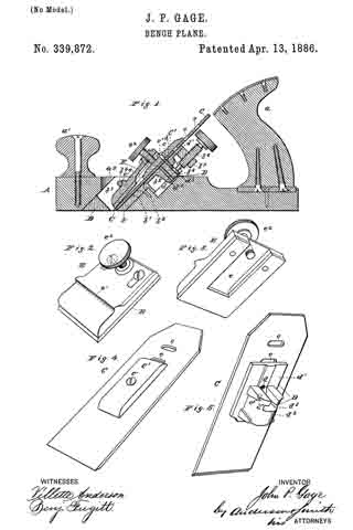
Figure 1 of the drawings is a representation of this invention, and is a vertical longitudinal section. Fig. 2 is a perspective view of one of the clamping-plates. Fig. 3 is another view of the same plate. Fig. 4 is a perspective view of the tool, and shows the clamp upon the upper side or front. Fig. 5 is a rear view of the tool, and shows the clamp upon the rear or under side.
This invention has relation to improvements in bench-planes; and it consists in the construction and novel arrangement of parts, hereinafter set forth, and pointed out in the claims.
The object of the invention is to provide a bench-plane in which the bit or cutting-tool may be properly adjusted both laterally and longitudinally, and when adjusted laterally the longitudinal movement will be in a straight line, and with its edge parallel to the lower surface of the plane-stock.
In the accompanying drawings, A designates the plane-stock, of rectangular shape, and provided with the handles a a’, firmly secured by screws or otherwise to its upper surface, and respectively near its front and rear ends.
a2 is the slot for the tool-holder in the plane-stock.
B is the holder for the bit or cutting-tool, secured in the slot a2. The holder B is provided with the inclined rear plate, b, secured in the slot a2 by means of the slots b’ and screws b2 and the parallel side plates, b3 b3, which lie against the side of the slot a2, and are connected by the transverse rod b4, as shown.
b5 is a larger longitudinal slot in the plate D, serving a purpose hereinafter explained, and b6 is an adjusting-screw, which engages a threaded opening in a stud, b7, on the rear surface of the top of said plate. The screw b6 has a suitable milled head on its upper end, and a circular or disk-like enlargement, b8 its lower end.
The tool-holder B is at its lower end flush with the lower surface of the stock, and has the usual transverse tool-opening in the said lower end.
If desired, the tool holder may be so made as not to extend through the stock.
C is the bit or cutting-tool, provided with the series of transverse slots c c and a proper cutting-edge at its lower end.
C’ is a clamping-plate, through a central opening in which the screw c’ passes. The said screw also passes through any one of the slots c of the tool, upon the front surface of which the clamp rests. The end of the screw c’ engages in one of the threaded openings d d in the guide-clamp D, which lies upon the rear surface of the tool C.
The clamp D consists of a rectangular plate, d’, and a guide-block, d2, on the rear surface of said plate. The block d2 has at its upper end the semicircular recess d3, open at top. Into this recess the disk b8 enters and turns freely therein, the block d2 passing through the slot b5 of the tool-holder. The sides of the block are squared, and made of proper dimensions to fit snugly within the slot.
It is evident from the foregoing that by turning the screw b6 up or down the cutting-tool C may be raised or lowered, and that the slot b5 will form a guide for the block d2 and for the tool clamped thereto by the means described, so that the edge of the tool, being made parallel to the lower surface of the stock, will always remain so, either when raised or lowered. Should the edge be not parallel to the bottom, the tool can be partially rotated between the clamps C’ and D’ by hand-pressure or by a light blow from a hammer, the screw c’ being loose enough to permit this. The slots c allow the position of the clamps C’ and D’ on the cutting-tool to be varied when necessary. Each slot c also allows the tool to be adjusted laterally between the clamps.
E is a clamping-plate of rectangular shape, and fitting into the tool-holder B between the side plates, b3. The plate E lies upon the tool C, and has a recess, e, on its inside surface for the reception of the clamping-plate C’.
e’ is a transverse shoulder on the outer surface of the plate E, which shoulder, when the plate is in position, rests upon the under side of the bar or rod b4.
e2 is a set-screw passing through a threaded opening in the plate E near its upper edge, and impinging upon the surface of the clamping-plate C’. The said screw does not possess sufficient hold on the plate to prevent the adjustment of the cutting tool.
By the construction described the necessity of setting the cutting-edge of the tool parallel with the bottom of the stock every time the said tool is moved or taken out is avoided, as the tool will keep permanently parallel therewith if the adjusting-clamp is not changed nor the cutting-edge worn unevenly.
Should the plate E be removed, the tool may at any time be taken out of the stock and replaced without altering the adjustment, as all the other parts must hold their relative positions to each other without the adjusting-screw b6 has its position changed.
Having described this invention, what I claim, and desire to secure by Letters Patent, is —
1. In a bench-plane, the combination, with the plane-stock, the tool-holder, slotted as described, and the adjusting-screw b, moving in a threaded opening in said tool-holder, of the tool C, the clamping-plate C’ on the outer side of the tool, and the clamp D on the under side thereof, the said clamp being provided with the block d2, passing through the slot b5 of the tool-holder and having the recess d3, which engages the disk b8 of the screw b, and the screw holding the clamp to the tool, substantially as specified.
2. In a bench-plane, the combination, with the plane stock and tool-holder, constructed as described, of the clamps C’ and D, the tool C, arranged between the said clamps and having the transverse slots c, and the screw c’, for securing the clamps to the tool, substantially as specified.
In testimony whereof I affix my signature in presence of witnesses.
JOHN PORCIUS GAGE.
Witnesses:
LEVERETT NEWCOMB,
LOUIS H. LEE,
ASAHEL GAGE.