
| PLEASE NOTE: The images presented on this page are of low resolution and, as a result, will not print out very well. If you wish to have higher resolution files then you may purchase them for only $2.95 per patent by using the "Buy Now" button below. All purchases are via PayPal. These files have all been cleaned up and digitally enhanced and are therefore suitable for printing, publication or framing. Each zip package contains all the images below (some packages may contain more), and purchased files can be downloaded immediately. |
UNITED STATES PATENT OFFICE.
_________________
CHARLES HENRY SLICER COLLINS, OF CLEVELAND, OHIO.
CORE-BOX PLANER.
_________________
SPECIFICATION forming part of Letters Patent No. 345,278, dated July 13, 1886.
Application filed March 17, 1886. Serial No. 195,610. (No model.)
_________________
To all whom it may concern:
Be it known that I, CHARLES HENRY SLICER COLLINS, a citizen of the United States, residing at Cleveland, in the county of Cuyahoga and State of Ohio, have invented a new and useful Improvement in Core-Box Planes, of which the following is a specification, reference being had to the accompanying drawings.
My invention relates to an improvement in core-box planes; and it consists in the peculiar construction and combination of devices, that will be morefully set forth hereinafter, and particularly pointed out in the claims.
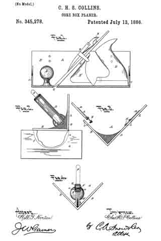
In the drawings, Figure 1 is a side elevation of my invention, partly in section. Fig. 2 is a front elevation of the same, showing the plane in operative position for planing a semi-cylindrical surface in a core-box. Fig. 3 is a detailed end elevation of the frame. Fig. 4: is a detail sectional view of the same, taken on the line x x of Fig. 1.
A represents the frame of the plane, which is composed of the metallic plates B, secured together at one edge and extending at right angles from each other. The plates B are connected at their front and rear ends by brace-plates C. In the angle formed by the two plates B, near the rear end of the same, is secured a handle, D, and in the angle formed by the two plates and near the front ends thereof is secured a projecting stud or standard, E, for the operator to take hold of with his left hand, his right hand grasping the handle D.
E’ represents a block, which is located in the angle formed by the plates B, and extends vertically midway between said plates. The front side of this block is inclined at an angle of about forty-five degrees, and is provided on opposite sides of the web of the block with flanges e, forming a broad bearing-face for the bit F, the point of which is beveled on opposite sides, as shown in Fig. 2, and extends through an opening, G, made between the converging edges of the plates B, in rear of the standard E.
H represents a clamp, which is provided with depending arms having inwardly-projecting studs that engage the under sides of the flanges e of the block E’, the said clamp having a spring, i, which bears on the upper side of the plane-bit, and provided with a thumb-latch, K, which is pivoted in the rear end of the clamp H and bears against the outer end of the spring. By this construction it will be readily understood that the plane-bit may be secured to the frame A at any desired adjustment, and moved in or out through the opening G in the said frame.
In Fig. 3, L represents extension-plates which are provided on one edge with extended arms M, through which arms pass screws N, that work in threaded openings O, made near the upper edges of the plates B, whereby the said extension-plates L may be secured to the outer edges of the plate B, or removed therefrom. By thus providing the extension-plates for the side plates of the frame of the plane, the latter is adapted for planing semi-cylindrical openings or grooves of any desired diameter.
The operation of the plane will be readily understood from an inspection of Fig. 2 and the foregoing description. The groove in the core-box a is first roughly gouged out, as shown, and the radius of the groove is drawn at each end of the core-box, as represented by the dotted lines c in said Fig. 2.
Having thus described my invention, I claim —
l. The combination of the frame having the rigid sides B, arranged at right angles to each ether, connecting by rigid brace-plates C, and the planing-bit projecting through an opening in the converging edges of the sides, and the extension-plates L, extending out at the same angle as the sides B, and means for securing the said plates to the outer edges of the sides, for the purpose set forth, substantially as described.
2. In a core-box plane, the frame comprising the rigid sides B, arranged at right angles to each other, the rigid plates C, connecting the sides at the ends, and the extension-plates L, secured to the outer edges of the sides B, and extending upward at the same angle as the sides, for the purpose set forth.
In testimony that I claim the foregoing as my own I have hereto affixed my signature in presence of two witnesses.
CHAS. HENRY SLICER COLLINS.
Witnesses:
JOSEPH GOBEILLE,
FREDERICK JABEZ RANDALL.