
| PLEASE NOTE: The images presented on this page are of low resolution and, as a result, will not print out very well. If you wish to have higher resolution files then you may purchase them for only $2.95 per patent by using the "Buy Now" button below. All purchases are via PayPal. These files have all been cleaned up and digitally enhanced and are therefore suitable for printing, publication or framing. Each zip package contains all the images below (some packages may contain more), and purchased files can be downloaded immediately. |
UNITED STATES PATENT OFFICE.
_________________
WILLIAM G. STRANAHAN, OF MINNEAPOLIS, MINNESOTA.
BLIND-NAILING PLANE.
_________________
SPECIFICATION forming part of Letters Patent No. 345,870, dated July 20, 1886.
Application filed November 14, 1885. Serial No. 182,808. (No model.)
_________________
To all whom it may concern:
Be it known that I, WILLIAM GALWAY STRANAHAN, of Minneapolis, in the county of Hennepin, State of Minnesota, have invented a certain new and useful Blind-Nailing Plane, of which the following is a full, clear, and exact description.
Prior to my invention, in blind-nailing it has been customary to use a chisel formed with two lips, in order to take up a small shaving from the surface of the wood, which shaving, after the introduction and driving of the nail, was returned to place and glued to the body of the wood; but not only was this a very slow way of doing the work, but the shaving was apt to be crumpled and narrowed, so that it did not fully fill up the cut, and the spot was liable to show.
With my improved form of instrument I am able to quickly form the shaving without in any way crumpling or narrowing it, so that when the nail has been driven the shaving may be returned to its original position, to be glued in place, and will entirely fill up the cut, so that after the operation is completed and the surplus glue removed it is impossible to locate the point where the nail has been driven.
The invention consists of a plane provided with a shuttle which carries a narrow knife, said shuttle being operated by a hand-lever, and the parts so arranged that the knife will project slightly through a longitudinal groove formed in the body of the plane, to strike against and out beneath the surface of the wood that is to be operated upon.
Reference is to be had to the accompanying drawings, forming a part of this specification, in which similar letters of reference indicate corresponding parts in all the figures.
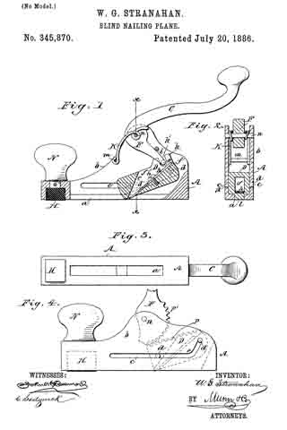
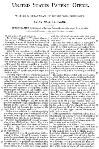
Figure 1 is a longitudinal vertical sectional view of my blind-nailing plane. Fig. 2 is a vertical cross-sectional view taken on line x x of Fig. 1. Fig. 3 is a view of the bottom of the plane. Fig. 4: is a view of a modified form of construction.
My preferred form of construction is illustrated in Figs. 1, 2, and 3, wherein A represents the plane-body, the bottom of which is formed with a narrow longitudinal groove, a. The side walls, b b, project upward from either end of the plane, and are each formed with a curved slot or way, c, said ways being parallel with the bottom of the plane until they reach a point, e, when they are curved upward and backward.
Between the walls b b there is arranged a shuttle, D, formed with a throat, f, and a knife-seat, f’, to which knife-seat the blade or knife h is secured by a set-screw, h’, the knife being, as usual , slotted to admit of proper adjustment.
Upon each side of the shuttle D there are two round lugs, d d, which fit within the curved ways or slots c, and upon the upper side of the rear end of the shuttle there is a nose-piece, k, formed with aslot, k’, within which the horizontal pins o of the lever F rest. This lever F is pivotally connected between the walls b b in substantially the position shown in Fig. 1, and is provided with a rearwardly-extending arm, C.
The shuttle D is provided with a projection, l, which fits closely within the slot a, the knife k being also formed to fit snugly between the side walls of said slot, but still to be capable of being moved between said walls. A wire spring, K, both ends of which are fixed to a pin, m, extends backward therefrom and is looped to embrace the pivotal point n of the lever F, from which point there is a stirrup-like loop, which passes back of the lever and below its manipulating-arm, so that when the lever is depressed the action of the spring will restore it to its normal position after the pressure is relaxed. Within a recess formed in the leading end of the plane, in front of the slot a, I secure a block of rubber, as shown at H, and upon the upper side of the forward end I affix a knob, N.
In the construction illustrated in Fig. 4 the shuttle shown as being formed with a toothed rack, p, and the lever F as being provided with a toothed segment, p’, which engages with the toothed rack of the shuttle.
The operation is as follows: The lower side of the plane is applied to the board or block which is to be nailed into place and pressed firmly against such board or block, a secure hold being obtained upon the knob N and the plane being prevented from slipping by the rubber block H. The manipulating-arm C is then pressed downward, and being so pressed will carry the lever F downward and forward, so that the knife h. will strike against the surface of the board or block and cut a thin shaving therefrom, which shaving will pass up through the throat f; but as the way c is parallel with the bottom of the plane the shaving will not be detached from the board, and as the lever-arm C is released it will be returned to the position shown in Fig. 1 by the action of the spring K; and as the knife k and the projection l of the shuttle D fit closely within the groove A the edges of the shaving will not be torn, nor will it be crumpled so as to be narrowed, and consequently, after the nail has been driven in the cut formed by the knife h, the shaving, when returned to place and glued within the cut, will completely fill it, and it will be almost impossible to discover where the cut was made. The upward motion of the lever F is limited by the pin i.
Having thus fully described my invention, what I claim as new, and desire to secure by Letters Patent, is —
1. The combination, with a plane-body formed with a longitudinal slot, a, of a shuttle carrying a knife, and an operating-lever, the shuttle working in the body with its knife extending into the slot a, substantially as described.
2. The combination, with a plane-body formed with a longitudinal slot, a, and side slots, c c, curved upward at their rear ends, of a shuttle carrying a knife and formed with lugs d d, working in the slots c c, and an operating-lever for reciprocating the knife in the slot a, substantially as described.
3. The combination, with a plane-body formed with a longitudinal slot, a, and side slots, c c, curved upward at their rear ends, of a shuttle carrying a knife and formed with lugs d d, an operating-lever, and a spring, substantially as described.
4. A blind-nailing plane in which the following elements are combined: a plane-body, A, formed with slot a and side slots, c c, curved upward at their rear ends, shuttle D, formed with lugs d d and a slot, k’, a knife, h, secured to the shuttle, a lever, F, manipulating-arrn C, and a spring, K, substantially as described.
5. A blind-nailing plane formed with a longitudinal groove, a, and side grooves, c c, a shuttle, D, formed with lugs d d and carrying a knife, as h, a lever, F, arm C, and block H, substantially as described.
WILLIAM G. STRANAHAN. [L. S.]
Witnesses:
JAMES F. STRANAHAN,
W. P. MORGAN.