
| PLEASE NOTE: The images presented on this page are of low resolution and, as a result, will not print out very well. If you wish to have higher resolution files then you may purchase them for only $2.95 per patent by using the "Buy Now" button below. All purchases are via PayPal. These files have all been cleaned up and digitally enhanced and are therefore suitable for printing, publication or framing. Each zip package contains all the images below (some packages may contain more), and purchased files can be downloaded immediately. |
UNITED STATES PATENT OFFICE.
_________________
JOHN L. DE HUFF, OF READING, MASSACHUSETTS.
ROUTER-PLANE.
_________________
SPECIFICATION forming part of Letters Patent No. 350,352, dated October 5, 1886.
Application filed February 20, 1886. Serial No. 192,667. (No model.)
_________________
To all whom it may concern:
Be it known that I, JOHN L. DE HUFF, of Reading, in the connty of Middlesex and State of Massachusetts, have invented certain new and useful Improvements in Router-Planes, of which the following is a specification.
My invention relates to planes used by pattern or cabinet makers, and particularly to what are known as “router-planes,” employed for grooving or channelling wood-work.
It is the object of my invention to construct a device of the character mentioned which shall be more serviceable than those heretofore employed, in that it will not be liable to become clogged or obstructed in its operations by shavings, may be readily adjusted to tools or plane-irons of different forms and sizes, and may have other points of advantage, all as hereinafter fully described, and subsequently pointed out in the claims.
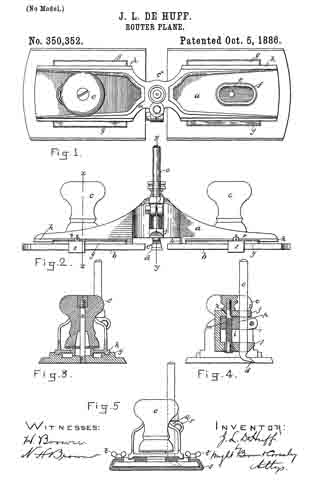
In the drawings hereto annexed and forming a part of this specification, Figure 1 represents a top plan view of my improved router-plane, one handle being shown as removed; Fig. 2, a front view; Fig. 3, a vertical section on the line x x, Fig. 2; Fig. 4, a section on the line y y, Fig. 2; and Fig. 5, an end view.
Similar letters of reference indicate similar parts in all of the figures.
In the drawings, a represents the stock of the plane, b, the sole thereof, c, the handles, and d the cutting-tool or plane-iron. As shown, the sole is formed in two equal sections, adjustable longitudinally on the stock by means of a screw-threaded stem or stud, e, secured to the upper surface of each sole-section a, which stem or stud projects through an elongated slot, f, in the stock, and upon which the handles are secured by being screwed thereon, as clearly represented in Figs. 3 and 5. A washer is preferably interposed between the base of the handle and the upper surface of the stock. By the construction described the stem or stud e serves the purpose of attaching the handle to the stock, and, inconnection with the handle, of clamping the sole-sections b to the stock proper at any point thereon within the limit of its adjustment, and an open channel, c*, from front to rear of the plane, is formed between the sole-sections. Each sole-section is provided on its upper surlhce with ribs g, extending along the sides thereof, as shown in Figs. 1 and 5, and the under surface of the stock proper, at both sides of its center, is provided with ribs h h’, the sides of which ribs are adapted to slide in correspondingly shaped grooves formed in the ribs g on the sole. (See Fig. 4.) Rib h’ on the under surface of the stock is constructed to move between the ribs g to form a close joint or connection between the stock and sole, and thus avoid liability of shavings becoming caught between the parts and obstructing the operations of the device. Any other construction and arrangement of ribs g and h to answer the same purpose would be within the scope of my invention.
The stock is cast or otherwise formed with a chamber, i, at its center, and with lugs j j projecting laterally from above and below said chambered part. Holes k and l are bored through the upper and lower portion of the chambered portion, and rod m, fitted to turn in holes k, is extended therethrough, as clearly shown in Fig. 4. Said rod is screw-threaded on that portion passing through the chamber, and is so stepped in the lower portion of the stock proper as to turn or rotate in holes k, but not to move vertically therein, a head, n, being secured to the upper end of said rod, whereby it maybe rotated. The holes l in the lugs j are adapted to receive the stem o of the plane-iron or cutting-tool. The screw-threaded portion of the rod in passes through a corresponding screw-threaded hole in a traveler, p, within chamber i, whereby by turning said rod said traveler may be raised or lowered thereon within said chamber. Said traveler is provided with a split clamp-extension q, through which the stem of the plane-iron is adapted to pass, and in which it is adapted to be clamped or secured by means of a bolt passing through ears r of said split clamp portion.
It will now be understood that a cutting tool or iron of any character may be secured in the clamp of the traveler at any horizontal angle therein, and adjusted by means of the rod on to any desired height, while the sole parts b b of the stock can be adjusted to a position as close to or far from the tool as the size or form of the cutting portion of the planer-iron may require.
Experience has demonstrated that a router-plane constructed in accordance with my invention is serviceable in the highest degree in all the uses for which a tool of that character is designed, and that there is no liability of the device becoming clogged or obstructed in its operation by shavings or chips cut from the material being operated upon. The edges of the soles are given a sloping form, and a gage, s, grooved to fit said edges, is secured thereon by means of thumb-screws t, as shown in the drawings. This gage is adapted to operate against the edge of the material being grooved or channeled, by which means the groove may lie formed in different pieces, the material at precisely the same distance from the edge, all as will be readily understood by those skilled in the art.
I do not confine myself or expect to be confined to the precise form and arrangement of parts shown and described, as these may be changed without departing from the spirit of the invention.
What I claim is —
1. A router-plane having its sole portion formed in two parts, one or both of said parts being adjustable longitudinally on the stock to and from the side or sides of the planer-iron or cutting-tool, as set forth.
2. A router-plane provided with a planer-iron or cutting-tool adjustable vertically therein, and having its sole portion formed in two parts longitudinally adjustable on both sides of the planer-iron or cutting-tool, as set forth.
3. The router-plane having flanges h h’, formed on its lower surface, and sectional sole portions a, having ribs g formed on their upper surfaces, said flanges h being adapted to move on ways on said ribs, and means for clamping or securing said sole portions to the stock at any desired position on both sides of the planer-iron or cutting-tool, as set forth.
4. A router-plane having its sole portion
formed in two parts, slots formed in the stock proper, studs or rods secured to the upper surface of said sectional sole parts and projecting through said slots, means for securing the handles of the planer to said studs and at the same time adjusting the sole parts at any desired point on the stock on one or both sides of
the planer-iron or cutting-tool, as set forth.
5. The combination, with the stock provided with the chamber i and lugs j, having the holes k and l formed therein, of the rod m, traveler p, provided with the split clamp portion q, having ears n, the clamping-bolt in said ears, and the cutting-iron d, as set forth.
In testimony whereof I have signed my name to this specification, in the presence of two subscribing witnesses, this 10th day of February, 1886.
JOHN L. DE HUFF.
Witnesses:
ARTHUR W. CROSSLEY,
C. F. BROWN.