
| PLEASE NOTE: The images presented on this page are of low resolution and, as a result, will not print out very well. If you wish to have higher resolution files then you may purchase them for only $2.95 per patent by using the "Buy Now" button below. All purchases are via PayPal. These files have all been cleaned up and digitally enhanced and are therefore suitable for printing, publication or framing. Each zip package contains all the images below (some packages may contain more), and purchased files can be downloaded immediately. |
UNITED STATES PATENT OFFICE.
_________________
FRANK M. BAILEY, OF NEW BRITAIN, CONNECTICUT, ASSIGNOR TO
THE STANLEY RULE AND LEVEL COMPANY, OF SAME PLACE.
BENCH-PLANE.
_________________
SPECIFICATION forming part of Letters Patent No. 350,613, dated October 12, 1886.
Application filed March 23, 1885. Serial No. 196,285. (No model.)
_________________
To all whom it may concern:
Be it known that I, FRANK M. BAILEY, a citizen of the United States, residing at New Britain, in the county of Hartford and State of Connecticut, have invented certain new and useful Improvements in Bench-Planes, of which the following is a specification.
My invention relates to improvements in bench-planes, and has particular reference to mechanism for adjusting the cutter.
The object of my invention is to provide a simple, convenient, and inexpensive mechanism for this purpose.
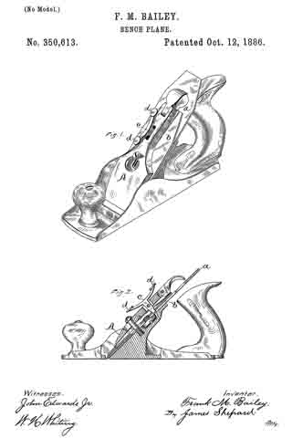
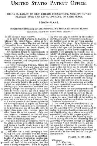
In the accompanying drawings, Figure 1 is a perspective view of a bench-plane showing my adjusting mechanism, and Fig. 2 is in part a longitudinal section through the adjusting mechanism and in part an elevation.
The plane in its general feature is of ordinary construction, of which a designates the cutting-bit-, b the cap-iron, and A the holding cap or clamp for holding the cutter in place. I pivot an angle-lever, c, in the body of the holding cap A, with one arm of said lever projecting through the holding-cap into a hole made to receive it in the cap-iron b in case of a plane having a double iron, or in the cutter itself or some part rigidly affixed thereto in case of a plane having a single iron. The outer end of the lever, as shown, has two arms, d d, which constitute the operating-handles for moving the lever to adjust the cutter up or down. These two handles are a convenience, as by pressing upon one of them the cutter is forced downward, while pressing upon the other forces the cutter upward. Only one arm, however, is necessary, as that will operate to adjust the cutter both ways by pulling outward or depressing said arm.
The main feature of my invention resides in the adjusting-lever pivoted to the holding-cap, and having a handle which forms a part of said lever upon the upper front side of said holding-cap.
I am aware that it is old to employ a lever having one arm connected with the cutter, while the other arm serves as an operating-handle of a plane-bit-adjusting mechanism, said lever being pivoted to the stock underneath and back of the cutting-bit, and the same is hereby disclaimed. Such an adjusting-lever can only be reached by the ends of one’s fingers, and is very inconvenient to operate, besides being in the way when grasping the handle of the plane. By my invention all the space under the frog and in front of the handle is left open and unobstructed, so that there is plenty of room for the fingers of the operator while grasping the handle, and no liability of hitting and hurting the fingers, as there is in planes having this space cramped by an adjusting mechanism. The construction is also very much simplified, so that the plane can be produced at a small cost. It also enables me to use a T form of lever when desired, so that the cutter can be adjusted both up and down by covering the two arms d d with the palm of one’s hand and bearing down upon either arm. Such a mode of adjusting cannot be employed when the adjusting-lever is placed back of and underneath the cutting-bit. Even with only one arm for an operating-handle, the lever is much more accessible and more conveniently operated than in any prior plane known to me.
I am also aware that an adjusting mechanism for a plane iron is shown in a prior patent as provided with an operating-screw for the adjusting mechanism, the handle of which screw is upon the upper front side of the holding cap or clamp, and I hereby disclaim the same.
I claim as my invention —
1. In a bench plane, the combination of the cutting-bit a, the holding cap or clamp A, and the adjusting-lever pivoted thereto and having its operating-handle on the upper front side of said holding cap or clamp, substantially as described, and for the purpose specified.
2. In a bench-plane, the adjusting angle-lever c, having one arm for connecting with the cutting-bit projected through the holding cap or clamp A and pivoted thereto, and the two arms d d, extending in opposite directions from the main arm upon the upper front side of the cap, to serve as operating-handles, substantially as described, and for the purpose specified.
FRANK M. BAILEY.
Witnesses:
H. S. WALTER,
CHAS. B. STANLEY.