
| PLEASE NOTE: The images presented on this page are of low resolution and, as a result, will not print out very well. If you wish to have higher resolution files then you may purchase them for only $2.95 per patent by using the "Buy Now" button below. All purchases are via PayPal. These files have all been cleaned up and digitally enhanced and are therefore suitable for printing, publication or framing. Each zip package contains all the images below (some packages may contain more), and purchased files can be downloaded immediately. |
UNITED STATES PATENT OFFICE.
_________________
WILLIAM HENRY BUSWELL, OF MANSON, IOWA.
RABBET-PLANE.
_________________
SPECIFICATION forming part of Letters Patent No. 351,689, dated October 26, 1886.
Application filed May 6, 1886. Serial No. 201,351. (No model.)
_________________
To all whom it may concern:
Be it known that I, WILLIAM HENRY BUSWELL, a citizen of the United States, residing at Manson, in the county of Calhoun and State of Iowa, have invented certain new and useful Improvements in Rabbet-Planes; and I do declare the following to be a full, clear, and exact description of the invention, such as will enable others skilled in the art to which it appertains to make and use the same, reference being had to the accompanying drawings, and to letters or figures of reference marked thereon, which form a part of this specification.
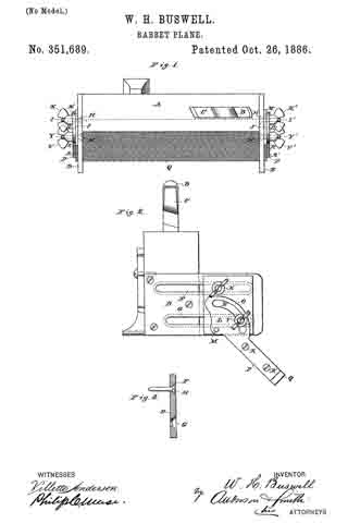
Figure 1 of the drawings is a representation of this invention, and is a top view. Fig. 2 is an end view. Fig. 3 is a detail, and is a vertical section through one of the cast-metal plates.
My invention relates to rabbet-planes designed for use in making rabbets of any desired depth and width in the material to be worked, without previously having to gage the rabbet or use a bevel-square; and the invention consists in the construction and novel combination of parts, as hereinafter described, and pointed out in the claim.
Referring by letter to the accompanying drawings, A designates the stock of the plane, which is provided with the bit-iron B, held in the stock by the wedge C, and the stock may be with or without a handle, according to the kind of plane-stock used. At its ends the stock A of the plane is provided with the cast-metal plates D and E, which plates are provided with longitudinal parallel slots F G, near their upper and lower edges, said slots extending nearly from end to end of said plates, the plates being beveled on their rear faces along the edges of the slots to form elongated countersinks, in which fit the heads H on the screw-stems I.
J J’ are rectangular plates secured to the enter faces of the slotted plates D E, said plates J J ‘ being held to their adjustments on the outer faces of the slotted plates D E by the screws I and thumb-nuts K K’.
L L’ are pivoted plates, secured to the rectangular sliding plates J J ’ by pivots M, passed through their lower inner corners. The pivoted plates L L’ are provided with arc slots N, in their cam-shape portions O, and from these cam-shape portions O project integral arms P, between which the gage-bar Q is secured by screws R R’, passed through holes in the arms P into the ends of the gage-bar Q.
By loosening the thumb-nuts K K’ the gage-bar can be moved in or out as far as the parallel slots will permit the slotted rectangular plates to slide.
By loosening the thumb nuts V V’ on the screws Y Y’, passed through the arc slots N, the gage-bar Q may be turned on its pivots, and be thereby caused to assume the required angle, after which the thumb-nuts V V’ may be tightened to hold the gage-bar at the angles to which it has been adjusted while the plane is being used. The upper edge of the gage-bar is beveled to fit the bottom of the plane and hold the gage-bar at the proper angle when said edge is moved under the stock of the plane.
Having described this invention, what I claim, and desire to secure by Letters Patent, is–
The improved rabbet-plane described, consisting of the stock A, the plates D E, having ing the parallel longitudinal slots and secured to the opposite ends of the stock in a plane relatively at right angles to the face thereof, the sliding rectangular plates J, held in sliding engagement with the said end plates by the transverse screws and nuts I K, the gage-bar, the plates R, having a semicircular slot, the thumb-nut working therein, an arm, P, for attachment to the ends of the said gage-bar, and their lower inner portions pivoted to a like point of the sliding end plates, substantially as specified.
In testimony whereof I affix my signature in presence of two witnesses.
WILLIAM HENRY BUSWELL.
Witnesses:
A. L. FUNK,
SOLOMON M. HEATH.