
| PLEASE NOTE: The images presented on this page are of low resolution and, as a result, will not print out very well. If you wish to have higher resolution files then you may purchase them for only $2.95 per patent by using the "Buy Now" button below. All purchases are via PayPal. These files have all been cleaned up and digitally enhanced and are therefore suitable for printing, publication or framing. Each zip package contains all the images below (some packages may contain more), and purchased files can be downloaded immediately. |
UNITED STATES PATENT OFFICE.
_________________
OSCAR E. HILDEBRAND, OF NORWICH, CONNECTICUT.
BEADING-TOOL.
_________________
SPECIFICATION forming part of Letters Patent No. 352,056, dated November 2, 1886.
Application filed July 15, 1886. Serial No. 208,051. (No model.)
_________________
To all whom it may concern:
Be it known that I, OSCAR, E. HILDEBRAND, a citizen of the United States, residing at Norwich, in the county of New London and State of Connecticut, have invented certain new and useful Improvements in Beading-Tools, which improvements are fully set forth and described in the following specification, reference being had to the accompanying drawings, in which —
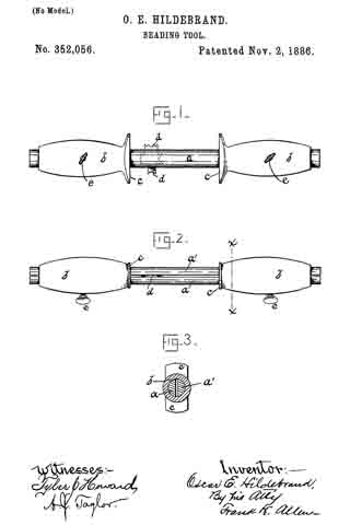
Figure 1 is a side view of said improved tool, and Fig. 2 a top view of the same. In Fig. 3 I have shown a transverse sectional view on line x x of Fig. 2.
My improvements are in that class of tools used commonly by cabinet makers and other wood-workers for grooving, channeling, or beading work, which cannot easily be done by machinery; and my object is to provide a practical tool, which shall be serviceable and strong, yet cheap.
My device is preferably constructed entirely of metal, the several pieces being of such shape I that they may be assembled with but little fitting.
Referring to the drawings, the letters a a’ represent rods, which are semicircular in cross-section and of sufficient length to receive at each end a handle, b, which handle I prefer to make of cast-iron. These handles are cored centrally throughout their length to slip over the two rods a a’, as will be understood by referring to Fig. 3, and are shaped at the irinner ends with flanges c c, which form gages to guide and control the movement of the knife when in use.
My cutting-tool proper is punched or otherwise formed from steel, and a single blank may have, if desired, several cutters of different designs on its opposite edges, as shown at d in Fig. 1. The cutter thus formed is entered between the flat sides of rods a a’, and the handles b are then adjusted to form the bead at the desired distance from the edge of the board, the depth of the cut being determined by the distance which the cutter projects below the rods. In order to clamp the parts thus adjusted firmly together, I have drilled and tapped the handles to receive clamping-screws e e, which, when screwed home, clamp the parts as rigidly as if they were integral with each other.
By forming my entire tool of metal, I find that the weight thus gained gives an impetus to the tool, which is desirable rather than objectionable, inasmuch as it requires less effort on the part of the operator. In many cases the thumb-screws e e may be dispensed with, the handles being forced onto rods a a’, which action squeezes the rods together sufficiently to hold the cutter; but as a rule I prefer to use clamping-screws, as shown.
Having described my invention, I claim —
1. In a beading-tool, in combination with two companion rods, a cutter adapted to be clamped between said rods, as described, and handles cored to slip over said rods to clamp the said cutters, all being substantially as herein specified.
2. In combination with two semicircular rods, a cutter adapted to be clamped between said rods, and handles cored to slip over said rods, as described, said handles being provided with clamping-screws, by which the several elements may be clamped together, for the purpose specified.
3. In combination with two companion rods, a cutter adapted to be clamped between said rods, as described, handles cored to slip over the ends of said rods and formed with gage-flanges at their inner ends, and thumb-screws or similar means for clamping the several parts together, substantially as herein set forth, and for the purpose specified.
OSCAR E. HILDEBRAND.
Witnesses:
FRANK H. ALLEN,
TYLER J. HOWARD.