
| PLEASE NOTE: The images presented on this page are of low resolution and, as a result, will not print out very well. If you wish to have higher resolution files then you may purchase them for only $2.95 per patent by using the "Buy Now" button below. All purchases are via PayPal. These files have all been cleaned up and digitally enhanced and are therefore suitable for printing, publication or framing. Each zip package contains all the images below (some packages may contain more), and purchased files can be downloaded immediately. |
UNITED STATES PATENT OFFICE.
_________________
HENRY F. STEARNS, OF SARATOGA SPRINGS, NEW YORK, ASSIGNOR OF
ONE-HALF TO EDMOND G. RAWSON, OF SAME PLACE.
ROUTING-TOOL.
_________________
SPECIFICATION forming part of Letters Patent No. 356,429, dated January 18, 1887.
Application filed June 22, 1885. Serial No. 169,356. (No model.)
_________________
To all whom it may concern:
Be it known that I, HENRY F. STEARNS, a citizen of the United States, residing at Saratoga Springs, in the county of Saratoga and State of New York, have invented certain new and useful Improvements in Routing-Tools for Workers of Wood, of which the following is a specification.
My invention relates to improvements in routing-tools in which the stock is provided with a mouth having on one of its sides a way for holding the cutting-tool and a wedging-piece and an adjustable gage working in the arms of the tool, all of which I will hereinafter particularly describe and set forth; and the objects of my invention are to provide in a routing-tool adjustable and interchangeable cutting-tools, which will be securely held from shifting in the mouth of the tool and have the gaging devices adapted to be variously adjusted and set at either right or left hand side of the cutting-tool and at any desired distance therefrom as the work to be done may require. I attain these objects by the mechanism illustrated in the accompanying drawings, in which —
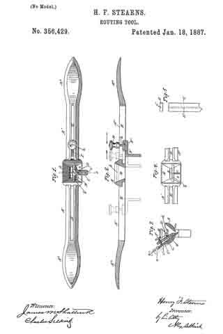
Figure 1 is a view of the tool from above. Fig. 2 is a longitudinal sectional elevation. Fig. 3 is a cross-section taken at line 1 in Fig. 1. Fig. 4 is a view of the mouth of the stock with the cutting-tool and wedge removed, and showing the tool-guiding way. Fig. 5 is a plan view of a cutting-tool and an end view of the same, showing the coacting way made therein.
The same letters of reference refer to like parts throughout the several views.
The stock A, arms A’, and handles A2 A2 of this tool may be made in one piece of malleable iron, or be made of wood and iron combined, if preferred. The stock A is made with a gradually-contracting mouth, B. Across the upper portion of this mouth, and arranged slightly to one side of the center of its width and running longitudinally in direction of arms A’, is bar b, preferably made solid with the end walls of said mouth, or securely fixed therewith. Made with the rear side wall, a, of this mouth is the way c, which is shown in Figs. 3 and 4 to project a short distance past the plane of said rear wall.
C is the cutting-tool, made with any form of cutting bit or edge usually employed for grooving, channeling, beading, or forming moldings, or for incising. Made central in the width of this cutting-tool and in its rear side from its upper end, or near the cutting bit or edge, is the way c’, corresponding in size and form with way c, made with the rear wall, a, of mouth B, so that the former will receive the latter and permit the shank of the tool to have a full bearing on the surface of wall a of the mouth of the tool. These ways may be made to be reversed in their respective forms by making that in wall a of mouth B in the form of a groove instead of a projection, as shown, and that in tool C in the form of a projection instead of a groove, as shown. These ways c c’ in the respective pieces co-operate together to hold the cutting tool or blade C from shifting or being moved out from its normal set position in the mouth of the stock, and allow a variety of tools or blades, C, of differing widths to be employed within mouth B without the least liability of shifting when the tool is being operated.
D is the wedge, having a shallow groove, d, running across its front side, as shown in Fig. 3, for engagement with holding-bar b. The lower end of this wedge is made with an incline, as shown in the same figure, so as to permit an opening between the tool or blade below and the front wall of mouth B, for passage of the shavings from the cutting bit or edge of the blade C. In the upper end portion of this wedge D is made a screw-threaded hole, into which works the set-screw f by which, through wedge D, the cutting tool or blade C is securely held in its adjusted position and length of projection below the sole or face m, of the stock, which face is curved in its surface. Made in arms A’ A’ are slots E E, extended to any preferred distance from stock A toward handles A2.
F is an adjustable gage-lip provided with a projection, g, which nicely fits in slots E, for holding with the same to prevent the gage-lip from shifting sidewise. This projection is made with tail-piece F’ of the gage-lip, and has projecting upward from it the screw-threaded stem h. Nicely fitting this stem h is the screw-threaded finger-nut H, for securing this gage-lip at any point distant from the cutting tool or blade C. This gage-lip and its holding device are adapted to be used in the slot E of either of the arms A’, as may be required for right or left hand work.
By my above described improvements I obviate the use of several different bodies of routing-tools as heretofore required by carriage-makers, cabinet-makers, and other workers of wood for different operations or kinds of work, and with a variety of cutting blades or tools, C, provided each with a suitable form of cutting edge or bit, a workman can form in the wood on straight or curved lines, and on the right or left hand edges of the pieces, grooves, channels, beads, moldings, flutings, or other raised or sunken surfaces, as may be required.
The mouth of the router, being arranged to be vertically over the cutting-bit of tool C, will deliver the shavings upward from the same in a free manner instead of in a forward direction, as is usual in routers heretofore made, and the shavings will be freely delivered from the cutting-bit and without the least liability of choking the tool, as heretofore. The coacting ways c c’, made with the rear side wall of the mouth of the stock and the rear side of the shank of the cutting-tool C, operate to hold that tool firmly from shifting in any direction, and the bar b, operating with the groove d of wedge D, holds the latter from moving in either direction end wise, While the wedge D, with the set-screw f operates to hold the tool or blade C secure to its place, with its cutting-edge projecting below the sole of the stock to the point adjusted to without the least liability of its being raised, and also allows this cuttlng-blade to be readily set to cut deeper from time to time, as may be required in the progress of the work.
The spokeshave-blade can readily be applied and be firmly held and shifted in either direction in relation to the month of the stock A. The stock, with its slotted arms and handles, operating to serve as the body of a spoke-shave, being well adapted to receive the above-described shaving-blade S, obviates the use and expense of a special and individual stock, as heretofore required.
The stock A and its mouth B may be made of any suitable length, so as to receive two or more cutting-tools, C, for grooving or incising or beading two or more surfaces at a time, as may be preferred. The curved surface of face m of the stock running from one side to the other enables the operator, by slightly turning the stock, to cut with a greater or less depth into the wood, and thereby obviates the necessity of setting the cutting-blade C (for making different depths of cuts) several times before finishing the work being done.
If preferred, a small bracket, z, made with the rear side of the stock, and provided witli a set-screw, x, working in its head end, and its lower end working in a small sleeve attached to the upper end of the tool C and held by a key, may be employed ibr raising or lowering the tool, as is the practice with irons in planes.
Having described my invention, what I claim, and desire to secure by Letters Patent, is —
In a routing-tool, the combination, with a stock provided with similarly-slotted arms, which are extended in opposite directions from the tool mouth, of an adjustable gage-lip, which is provided with a screw-threaded stem and nut and constructed to be used interchangeably in said slotted arms, a cutting-blade which is provided on its rear side with the way c’, which engages with way c, made with the rear side wall of tool-mouth B, and the mechanism described for adjusting and securing said cutting blade in said tool-mouth, substantially as and for the operations and purposes set forth.
HENRY F. STEARNS.
Witnesses:
A. N. SHEPHERD,
W. A. PIERSEN.