
| PLEASE NOTE: The images presented on this page are of low resolution and, as a result, will not print out very well. If you wish to have higher resolution files then you may purchase them for only $2.95 per patent by using the "Buy Now" button below. All purchases are via PayPal. These files have all been cleaned up and digitally enhanced and are therefore suitable for printing, publication or framing. Each zip package contains all the images below (some packages may contain more), and purchased files can be downloaded immediately. |
UNITED STATES PATENT OFFICE.
_________________
JUSTUS A. TRAUT, OF NEW BRITAIN, CONNECTICUT, ASSIGNOR TO
THE STANLEY RULE AND LEVEL COMPANY, OF SAME PLACE.
BENCH-PLANE.
_________________
SPECIFICATION forming part of Letters Patent No. 376,455, dated January 17, 1888.
Application filed July 23, 1887. Serial No. 245,062. (No model.)
_________________
To all whom it may concern:
Be it known that I, JUSTUS A. TRAUT, a citizen of the United States, and a resident of New Britain, in the county of Hartford and State of Connecticut, have invented certain new and useful Improvements in Bench-Planes, which improvements are so described in detail in the following specification as to enable others skilled in the art to which they pertain to make and use the same, reference being also had to the annexed sheet of drawings, in which —
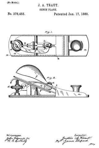
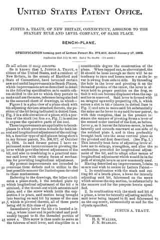
Figure 1 is a plan view of a plane-stock with bit-adjusting devices attached thereto, the position of the bit being indicated in dotted lines. Fig. 2 is a side elevation of a plane, with a portion of the stock (on line x x, Fig. 1) in section to expose the operative parts of the tool.
These improvements are applicable to bench-planes in which provision is made for both lateral and longitudinal adjustment ofthe cutting-bit, a familiar type of said planes being shown in my former patent, No. 306,877, of October 11, 1884. In said former patent I have experienced some inconvenience in pivoting the lever which provides lateral adjustment of the bit, and also in combining in a practical manner said lever with certain forms of mechanism for providing longitudinal adjustment.
My present improvements are intended to overcome these defects and to utilize in the best possible manner the limited space devoted to these mechanisms.
Referring to the drawings, the letter a indicates a plane-stock, b the notched plate by which longitudinal adjustment of the bit c is attained, d the thumb-nut which actuates said plate, and e the screw which holds the cap-section k in place, said section being brought into bearing on said bit by means of the cam f which is pivoted thereto, all of these parts being old in this class of planes.
Immediately below the bit c is located a lever, g, whose inner end is perforated and preferably tapped to fit the threaded portion of screw e. This screw is thus made to serve as the fulcrum of said lever, and simplifies in a considerable degree the construction of the plane. When tapped out, as above stated, the fit should be loose enough so there will be no tendency to turn and loosen screw e as the lever is swung from side to side. By threading the hole in the lever and pivoting it on the threaded portion of the screw, the lever is always held in proper position on the frog, so that it will not become displaced when the cap-section is removed. Said lever is formed with an integral upwardly-projecting rib, h, which enters a slot in bit c (shown in dotted lines in Fig. 1) and acts to move said bit substantially the same as the lever in my said former patent, with this exception, that in the present instance the manner of pivoting forms a lever of the second order instead of the first, as before. Lever g, as it leaves the fulcrum-screw, is bent laterally and extends rearward at one side of the notched plate b, and is then preferably brought back into the same vertical plane as the pivoted end first described. (See Fig. 1.) This laterally-bent form of adjusting-lever allows me to enlarge, strengthen, and alter the mechanism provided for longitudinal adjustment of the bit, and to adopt other means of longitudinal adjustment which would lie in the path of straight levers as now commonly used.
Having described my improvements, I claim as new and wish to secure by Letters Patent —
1. In combination with the stock and cutting-bit of a bench-plane, a lever for laterally adjusting said bit, fulcrumed on the screw which secures the cap section, in substantially the manner and for the purpose herein specified.
2. In combination with the stock and bit of a plane, a lever for laterally adjusting said bit, said lever being tapped to fit and fulcrumed on the cap-screw, substantially as and for the objects specified.
JUSTUS A. TRAUT.
Witnesses:
H. S. WALTER,
F. N. STANLEY.