| PLEASE NOTE: The images presented on this page are of low resolution and, as a result, will not print out very well. If you wish to have higher resolution files then you may purchase them for only $2.95 per patent by using the "Buy Now" button below. All purchases are via PayPal. These files have all been cleaned up and digitally enhanced and are therefore suitable for printing, publication or framing. Each zip package contains all the images below (some packages may contain more), and purchased files can be downloaded immediately. |
UNITED STATES PATENT OFFICE.
_________________
JOHN H. SHAW, OF NEW HAVEN, CONNECTICUT, ASSIGNOR TO
SARGENT & COMPANY, OF SAME PLACE.
BENCH-PLANE.
_________________
SPECIFICATION forming part of Letters Patent No. 377,645, dated February 7, 1888.
Application filed July 5, 1887. Serial No. 243,353. (No model.)
_________________
To all whom it may concern:
Be it known that I, JOHN H. SHAW, of New Haven, in the county of New Haven and State of Connecticut, have invented a new Improvement in Planes; and I do hereby declare the following, when taken in connection with accompanying drawings and the letters of reference marked thereon, to be a full, clear, and exact description of the same, and which said drawings constitute part of this specification, and represent, in —
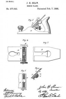
Figure 1, a side view of the plane complete; Fig. 2, a face view of the plane-iron bed, showing the transverse adjusting-screw; Fig. 3, a back side view of the plane-iron; Fig. 4, a vertical section through the transverse adjusting-screw and in the slot of the plane-iron; Fig. 5, a modification in the support of the transverse adjusting-screw.
This invention relates to an improvement in that class of planes in which the stock is made from metal, and is provided with means for adjusting the plane-iron to give a greater or less cut. Usually the only adjustment made by the mechanism of the plane itself is to produce a greater or less extent of cut by the plane-iron; but in setting the plane-iron a lateral adjustment is necessary. This is generally produced by means of a hammer striking the edge of the plane-iron to turn it to the right or left, as the case may be, to bring it into proper relation to the face of the plane. A device has been applied to the plane by which the lateral adjustment may be produced mechanically, this device consisting of a lever hung upon the stock and engaged with the iron, so that by turning the lever to one side or the other the plane-iron will be thrown accordingly; but this adjustment is liable to displacement by accidental blows upon the lever, and is not capable of that nice adjustment which is necessary in setting the iron, and is inconvenient in many respects. In another case an endless screw has been transversely arranged across the stock of the plane, and in engagement with the same lever by which the cut of the plane is adjusted; but in this construction the adjustment by one screw is liable to be deranged by the adjustment of the other screw, because of both screws acting in different directions upon the same lever.
The object of my invention is to apply a screw for the transverse adjustment of the iron, but independent of the cut-adjusting device, whereby the nicest adjustment may be produced without liability of accidental displacement.
A represents the stock, which may be any of the usual or known constructions, and in which the plane-iron B is arranged in the usual manner and secured by any suitable device.
C represents the adjusting-screw by which the plane-iron is adjusted to produce a greater or less cut — a common and well-known device, and does not require particular description. The stock is provided with a solid bed, D, upon which the plane-iron rests, also in the usual manner. In the stock, above the point where the adjusting device engages the plane-iron, (E representing the opening in the bed through which the adjusting device engages the iron,) I arrange a transverse screw, F, there being a transverse recess, G, formed across the bed for this purpose. In the recess in the bed one or more bearings, a, are formed for the screw, the seats in these bearings being of less diameter than the body of the screw. The screw itself is constructed with annular grooves b, corresponding to the bearings a, and so that laid into the bearings, as indicated in Fig. 2, the screw may rotate in the bearings, but held by the bearings against movement in an axial direction.
The outer end of the screw is provided with a suitable head, H, by which it may be turned. On the screw is a nut, I, adapted to slide through the recess in which the screw is applied, the nut being internally screw-threaded corresponding to the thread of the screw, and because the nut can not revolve in the recess, owing to its shape, as seen in Fig. 4, it follows that the rotation of the screw will impart to the nut a transverse movement, according to the direction in which the screw is turned. The nut projects above the face or bearing-surface of the bed and enters the slot J in the plane-iron B, the length of the nut corresponding to the width of the slot, the slot being of a standard width in all irons adapted to a certain size plane.
When the plane-iron is secured in the stock in the usual manner, if it be desired to impart transverse movement to the iron in either direction, the screw H is turned accordingly, and through the nut I imparts such required transverse movement to the plane-iron, and when once set there is no liability of accidental dis-adjustment, and the most perfect adjustment may be made by the screw, much more so than can be produced by a lever which is turned by hand or by blows imparted to it.
The bearings a in the recess in the bed are equidistant from the center, so that the screw may be introduced with its head either to the right or left, as indicated in Fig. 2, solid lines indicating the left-hand position and broken lines the right-hand position. The bearings are simply of U shape, open outward, as seen in Fig.2, so that the screw may be dropped therein. The adjusting device is therefore readily removable from the plane should occasion require.
It will be understood that the transverse adjustment may be applied to a plane with any of the many different vertical adjustments, or without vertical adjustment should it be desired.
While I prefer to construct the recess with the bearings a, into which the screw may be dropped or readily removed, as I have described, it may be supported permanently in the recess, as seen in Fig. 5, it only being essential that when the screw is in its place it shall be prevented from movement in an axial direction, yet left free for rotation, and carry the nut.
From the foregoing it will be understood that I do not claim, broadly, the combination, in a plane, of a transverse or lateral adjusting-screw for the plane-iron.
I claim —
In a plane substantially such as described, the bed upon which the plane-iron rests, constructed with a transverse recess, G, and with one or more bearings, a, therein, combined with a screw, F, constructed with annular groove or grooves corresponding to said bearing or bearings and adapted to set therein, the said screw provided with a head upon its outer end, by which it may be rotated, a nut, I, in said recess and upon said screw, but independent of the cut-adjusting mechanism, the said nut adapted to engage the plane-iron, substantially as and for the purpose described.
JOHN H. SHAW.
Witnesses:
OTTO SCHLIEPER,
CHAS. L. BALDWIN.


