| PLEASE NOTE: The images presented on this page are of low resolution and, as a result, will not print out very well. If you wish to have higher resolution files then you may purchase them for only $2.95 per patent by using the "Buy Now" button below. All purchases are via PayPal. These files have all been cleaned up and digitally enhanced and are therefore suitable for printing, publication or framing. Each zip package contains all the images below (some packages may contain more), and purchased files can be downloaded immediately. |
UNITED STATES PATENT OFFICE.
_________________
JOHN J. TOWER, OF BROOKLYN, NEW YORK.
PLANE.
_________________
SPECIFICATION forming part of Letters Patent No. 379,346, dated March 13, 1888.
Application filed November 1, 1886. Serial No. 217,674. (No model.)
_________________
To all whom it may concern:
Be it known that I, JOHN J. TOWER, of Brooklyn, in the county of Kings and State of New York, have invented an Irnprovement in Planes, of which the following is a specification.
Bench planes are extensively manufactured with wooden handles fastened into a metal plate that is screwed upon the wooden body of the plane, and this plate extends forward of the handle and is provided with vertical flanges, between which the plane-iron is received. Difficulty has heretofore been experienced in attaching the handle in such a manner that the same will not work loose when in use and so that the handle can be disconnected with facility for packing or be rapidly and firmly replaced. I make use of a screw passing through the handle at an inclination to the plane, so as to strengthen the handle, and this screw enters the iron plate so as to clamp the handle thereto, and the bottom portion of the handle is extended forward and passes in between undercut lugs upon the iron plate, so that the weight of the plane when it is lifted by the handle is partially taken upon the undercut lugs, and any tendency to bend the screw is prevented and the thrust upon the handle when the plane is in use is received jointly by the clamping-screw and the undercut lugs.
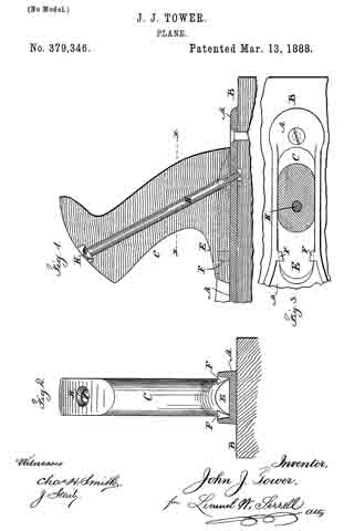
In the drawings, Figure 1 is a section through the handle and part of the iron plate. Fig. 2 is a cross-section of the plate and an elevavation of the handle; and Fig. 3 is a sectional plan below the line x x, Fig. 1.
The plate A is usually of iron and provided with side flanges, between which the plane-iron is received, and my improvement is available with planes having a face formed of the iron plate; but l have shown the said iron plate as fastened to a wooden base, B, forming the face of the plane.
The handle C is of wood or similar material and of the desired shape for being grasped by the hand. The long part of the handle is extended forward, as at E, and its edges are inclined inwardly.
Upon the plate A are straight parallel flanges having the lugs F, which are in a position adjacent to the forward part of the base of the handle. These lugs are undercut or dovetailed, which can be most conveniently effected by a rotary cutter, so that the inner faces of the lugs correspond to the inclined sides of the bottom and forward part of the handle, and the handle is to be slipped in between the straight parallel flanges, and the forward end passes below the said lugs.
There is a hole passing through the handle in a position diagonal to the plate A, and the screw H, having a countersunk head, is passed through this handle into a threaded hole in the plate A. By this means I am able to firmly attach the handle to the plate and to allow for removing the handle with facility for packing the plane or for replacing the handle when desired for use, and the handle is not weakened by any dovetailed grooves on its edges.
In cases where a screw has been passed through the handle the weight and leverage of the plane tend to bend the screw, and when dovetailed ribs on the iron plate have received the edges of the handle such edges have been grooved on a bevel and the handle weakened, and there is nothing to prevent the handle drawing back out from the ribs.
By my improvement the lugs F only pass over the forward lower end of the handle, but they effectually hold this end from lifting and with the screw form a strong and reliable attachrnent.
If a screw were passed through the forward lower end of the handle, it would not hold the parts as strongly and reliably as the dovetail lugs.
I claim as my invention —
The combination, with the plane-handle and the screw passing through the sarne, of a metal plate into which the screw passes, and which plate has straight parallel flanges for receiving between them the lower part of the handle, and the lugs F, that come over the forward beveled end of the base of the handle, substantially as set forth.
Signed by me this 26th day of October, 1886.
JOHN J. TOWER.
Witnesses:
GEO. T. PINCKNEY,
WILLIAM G. MOTT.


