
| PLEASE NOTE: The images presented on this page are of low resolution and, as a result, will not print out very well. If you wish to have higher resolution files then you may purchase them for only $2.95 per patent by using the "Buy Now" button below. All purchases are via PayPal. These files have all been cleaned up and digitally enhanced and are therefore suitable for printing, publication or framing. Each zip package contains all the images below (some packages may contain more), and purchased files can be downloaded immediately. |
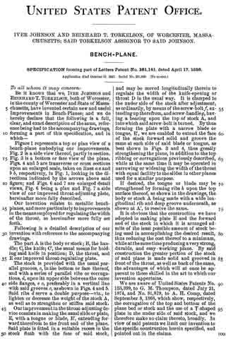
UNITED STATES PATENT OFFICE.
_________________
IVER JOHNSON AND REINHARD T. TORKELSON, OF WORCESTER, MASSACHUSETTS;
SAID TORKELSON ASSIGNOR TO SAID JOHNSON.
BENCH-PLANE.
_________________
SPECIFICATION forming part of Letters Patent No. 381,141, dated April 17, 1888.
Application filed October 31, 1887. Serial No. 253,829. (No model.)
_________________
To all whom it may concern:
Be it known that we, IVER JOHNSON and REINHARD T. TORKELSON, both of Worcester, in the county of Worcester and State of Massachusetts, have invented certain new and useful Improvements in Bench-Planes; and we do hereby declare that the following is a full, clear, and exact description of the same, reference being had to the accompanying drawings, forming a part of this specification, and in which–
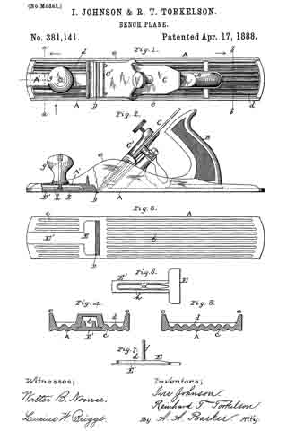
Figure 1 represents a top or plan view of a bench-plane embodying our improvements. Fig. 2 is a side view thereof, partly in section. Fig. 3 is a bottom or face view of the plane. Figs. A and 5 are transverse or cross sections upon an enlarged scale, taken on lines a a and b b, respectively, in Fig. 1, looking in the directions indicated by the arrows above said figure; and Figs. 6 and 7 are enlarged detail views, Fig. 6 being a plan and Fig. 7 a side view of our improved throat-adjusting plate, hereinafter more fully described.
Our invention relates to metallic bench-planes, and more particularly to improvements in the means employed for regulating the width of the throat, as hereinafter more fully set forth.
Following is a detailed description of our invention with reference to the accompanying drawings.
The part A is the body or stock; B, the handle; C, the knife; C’, the usual means for holding said knife in position; D, the throat, and E our improved throat-regulating plate.
The stock is provided with the usual parallel grooves, c, in the bottom or face thereon and with a series of parallel ribs or corrugations, d, upon its upper side between the outer side flanges, e e, preferably in a vertical line with said grooves c, as shown in Figs. 4 and 5. Said ribs d serve a double purpose — viz., to lighten or decrease the weight of the stock A, as well as to strengthen or stiffen said stock.
Our improvement in the throat-adjusting device consists in making the usual slide or plate, E, with a tongue or blade, E’, extending forward therefrom to the front end of the plane. Said plate is fitted in a suitable recess in the stock flush with the face of said stock, and may be moved longitudinally therein to regulate the width of the knife-opening or throat D in the usual way. It is clamped to the under side of the stock after adjustment, as ordinarily, by means of the screw-bolt f, extending up therefrom, and screw-handle g, having a bearing upon the top of stock A, and into which said screw-bolt is turned. By thus forming the plate with a narrow blade or tongue, E’, we are enabled to extend the face of the stock forward solid and groove the same at each side of said blade or tongue, as best shown in Figs. 3 and 4, thus greatly strengthening the plane, in addition to the top ribbing or corrugations previously described, while at the same time it may be operated in narrowing or widening the width of the throat with equal facility to the slides in other planes used for a similar purpose.
If desired, the tongue or blade may be strengthened by forming ribs h upon the top surface thereof, as shown in the drawings, the body or stock A being made with a wide longitudinal rib and deep groove underneath, as Shown at A’, to receive the same.
It is obvious that the construction we have adopted in making plate E and the forward end of the stock in which it is arranged admits of the least possible amount of stock being used in accomplishing the desired result, thus reducing the cost thereof to a minimum, while at the same time producing a very strong, durable, and easy-working plane. By said construction the greater portion of the stock of said plane is made solid and grooved in front of the throat, as well as back of the same, the advantages of which will at once be apparent to those skilled in the art to which our invention appertains.
We are aware of United States Patents No. 153,399, to G. M. Thompson, dated July 21, 1874, and No. 81,879, to A. H. Comp, dated September 8, 1868, which show, respectively, the corrugation of the top and bottom of the plane bed or stock and the use of a T-shaped plate in the under side of said stock, and we therefore make no claim thereto, broadly. In view of said patents we limit our invention to the specific construction herein specified, and pointed out in the claims.
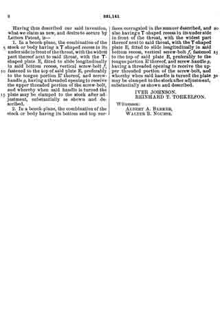
Having thus described our said invention, what we claim as new, and desire to secure by Letters Patent, is —
1. In a bench-plane, the combination of the stock or body having a T-shaped recess in its under side in front of the throat, with the widest part thereof next to said throat, with the T-shaped plate E, fitted to slide longitudinally in said bottom recess, vertical screw-bolt f fastened to the top of said plate E, preferably to the tongue portion E’ thereof, and screw-handle g, having a threaded opening to receive the upper threaded portion of the screw-bolt, and whereby when said handle is turned the plate may be clamped to the stock after adjustment, substantially as shown and described.
2. In a bench-plane, the combination of the stock or body having its bottom and top surfaces corrugated in the manner described, and also having a T-shaped recess in its under side in front of the throat, with the widest part thereof next to said throat, with the T-shaped plate E, fitted to slide longitudinally in said bottom recess, vertical screw-bolt f fastened to the top of said plate E, preferably to the tongue portion E’ thereof, and screw-handle g, having a threaded opening to receive the upper threaded portion of the screw-bolt, and whereby when said handle is turned the plate may be clamped to the stock after adjustment, substantially as shown and described.
IVER JOHNSON.
REINHARD T. TORKELSON.
Witnesses:
ALBERT A. BARKER,
WALTER B. NOURSE.