
| PLEASE NOTE: The images presented on this page are of low resolution and, as a result, will not print out very well. If you wish to have higher resolution files then you may purchase them for only $2.95 per patent by using the "Buy Now" button below. All purchases are via PayPal. These files have all been cleaned up and digitally enhanced and are therefore suitable for printing, publication or framing. Each zip package contains all the images below (some packages may contain more), and purchased files can be downloaded immediately. |
UNITED STATES PATENT OFFICE.
_________________
JUSTUS A. TRAUT, OF NEW BRITAIN, CONNECTICUT, ASSIGNOR TO
THE STANLEY RULE AND LEVEL COMPANY, OF SAME PLACE.
BENCH-PLANE.
_________________
SPECIFICATION forming part of Letters Patent No. 386,509, dated July 24, 1888.
Application filed April 17, 1888. Serial No. 270,273. (No model.)
_________________
To all whom it may concern:
Be it known that I, JUSTUS A. TRAUT, a citizen of the United States, residing at New Britain, in the county of Hartford and State of Connecticut, have invented a certain new and useful Improvement in Bench-Planes, which improvement is fully set forth and described in the following specification.
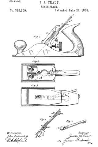
Reference is also made to the sheet of drawings annexed hereto, in which Figure 1 is a side elevation of a plane having my improvement embodied therein. Fig. 2 is a sectional detail view of the same on line x x of Fig. 1, and Fig. 3 is a like view with the cutting-bit attached. Fig. 4 is a sectional detailed view on a central longitudinal line. Fig. 5 is a detached perspective view of the lever by means of which the cutting-bit is rocked or adjusted laterally, as hereinafter explained.
The class of planes to which my invention relates is that in which the cutting-bit may be adjusted laterally relative to its seat for the purpose of bringing the cutting-edge of said bit parallel with the throat, or, in other words, square with the plane-stock. A familiar type of said class is shown and fully described in my Patents No. 306,877 issued October 21, 1884, and No. 376,455, January 17, 1888, to which patents reference is hereby made.
The object of my present invention is to improve the construction of the lever employed to adjust the bit laterally, so that said device may work easier and with less friction than heretofore. To produce this desired result I have secured to the bit-engaging end of the adj usting-lever an anti-frictional disk that partially rotates on its axial pivot, as I will proceed to describe.
The letter B denotes the cutting-bit; A, the seat provided for said bit in the so-called “frog” of the plane, and C the cap-iron.
a indicates my new form of lever provided to adjust the bit in a lateral direction. Said lever is perforated, as at a’, to slip over a pin, a2, near the rear end of the bit-seat A, said pin forming the fulcrum on which the lever swings. The bit-seat is recessed, as atb, to receive said lever, said recess being of such depth that the lever may move freely between the bit and frog when the several parts are assembled for use. The lower or short arm of lever a has pivoted to its bit-engaging side a disk, c, that may rotate freely on its pivot. This disk, when the parts are assembled, projects upward into the bit slot d. (See Figs. 3 and 4.)
When it is desired to adjust the bit to square it with the plane-stock, the free end of lever a is swung to one side — as, for example, in Fig. 3 — which action moves the short arm of said lever in the opposite direction, and the disk c carries with or before it the bit B. During this adjusting operation disk c partially revolves on its axial pivot, and so reduces in a considerable degree the friction of the engaging parts.
My device, as described, may be applied to planes of this class without any material changes, and does not add to the cost of such tools.
I claim as my invention —
In combination with the stock and bit of a plane, a lever for laterally adjusting said bit, and the rotary disk pivoted on the shorter arm of said lever and engaging the longitudinal slot of said bit, substantially as described, and for the purpose specified.
JUSTUS A. TRAUT.
Witnesses:
HENRY S. WALTER,
H. C. HINE.