
| PLEASE NOTE: The images presented on this page are of low resolution and, as a result, will not print out very well. If you wish to have higher resolution files then you may purchase them for only $2.95 per patent by using the "Buy Now" button below. All purchases are via PayPal. These files have all been cleaned up and digitally enhanced and are therefore suitable for printing, publication or framing. Each zip package contains all the images below (some packages may contain more), and purchased files can be downloaded immediately. |
UNITED STATES PATENT OFFICE.
_________________
ISAAC CAMIER, OF CHICAGO, ILLINOIS.
SPOKESHAVE.
_________________
SPECIFICATION forming part of Letters Patent No. 395,738, dated January 8, 1889.
Application filed September 29, 1887. Serial No. 251,083. (No model.)
_________________
To all whom it may concern:
Be it known I, ISAAC CAMIER, a citizen of the United States, and a resident of Chicago, in the county of Cook and State of Illinois, have invented certain new and useful Improvements in Spokeshaves; and I do hereby declare the following to be a full, clear, and exact description of the same, reference being had to the accompanying drawings, forming a part of this specification, and in which —
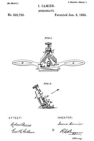
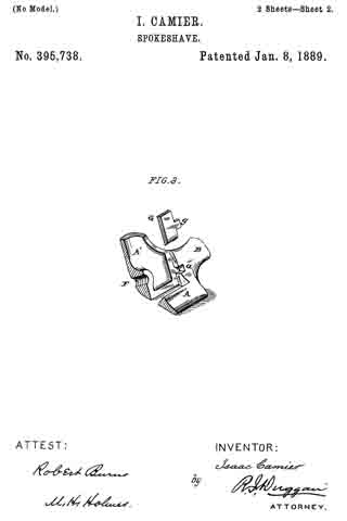
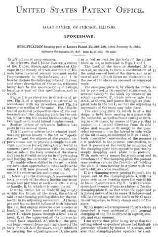
Figure 1. is an elevation in direction of arrow, Fig. 2, of a spokeshave constructed in accordance with my invention, and Fig. 2 a transverse section of the same. Fig. 3 is a detached sectional perspective view of the cutter-stock and the clamping-plate for the cutter, illustrating the means for connecting the two together to avoid lateral displacement.
Similar letters of reference indicate like parts in the several views.
This invention relates to that class of wood-working planes known in the art as “spoke-shaves;” arid the objects of the present improvements are to provicle a simple and efficient appliance for adjusting the cutter-bit in accurate parallel alignment with the bearing face or sole of the body or stock of the share, and also to furnish means for firmly clamping and holding the cutter-bit to its adjustment.
To enable others skilled in the art to which my invention appertains to make and use the same, I will now proceed to more fully describe its construction and operation.
Referring to the drawings, A represents the body or stock of the shave, having any usual shape and provided at each side with a wing or handle, B, by which it is manipulated.
C is the cutter bit or blade fitting snugly within the throat of the stock, the sides of said throat forming guiding-slides for the cutter-bit in its adjusting movement. At its upper end the cutter-bit is formed with inturned lips c c, that engage sidewise over a collar or head, d, on the lower end of the adjusting-screw D, which passes through a fixed nut or head, E, at the upper end of the horn or inclined back standard, A’ which in the present improvement forms an integral part of the body or stock A of the shave, and, in addition to carrying the adjusting-screw D, also acts as a bed or rest for the body of the cutter blade or bit, as indicated in Figs. 1 and 2.
The back ot the horn or standard A’ is curved, as shown, to form a continuation of the usual curved heel of the shave, and as so curved and inclined forms no obstruction to the use of the shave on recessed or concaved work.
The clamping-plate G, by which the cutter-bit is clamped in its required adjustment, is secured loosely to the stock by means of an attaching-screw, F, which screws into the stock, as shown, and passes through an elongated hole in the bit C, so that the adjusting movement of the same may take place.
The clamping-plate G, which is of a flat shape, is held from moving in a plane with the cutter-bit, as well as from turning or shifting in such plane, by means of lugs g g, that project in a lateral direction from its side edges and engage or fit snugly in the open-sided recesses a a in the lateral or side walls of the bit-throat, as indicated in Figs. 1 and 3. Such open-sided construction of the recesses a is material to the present construction, in that it permits of the ready introduction of the clamping-plate into operative position by simply dropping said plate into position. With such ready means for attachnient and detachment of the clamping-plate the present construction retains the function of holding the plate G from moving in a plane with the cutter-bit, as above mentioned.
H is a clamping-screw passing through the upper end of the clamping-plate G, with its point resting or bearing upon the cutter bit or blade C, as shown in Fig. 2. With this construction the screw F acts as a fulcrum for the clamping-plate G, so that when its upper end is forced outward by the screw H its lower end will be forced against the blade or bit C, near its cutting-edge, to firmly clamp and hold the same.
By my improved arrangement of parts above described a very substantial and general clainping of the bit is effected in a quick, simple, and easy manner.
I am aware that prior to my invention the cutting-bits of carpenters’ planes had their adjustment effected by means of a screw, and also that clamping-plates operated by a set-screw were employed to hold or clamp the bit to its adjustment. I therefore do not claim either of such constructions, broadly; but
What I do claim as my invention, and desire to secure by Letters Patent, is —
l. The combination, in a spokeshave, of the stock A, having open-sided recesses a a in the lateral walls of the bit-throat, the clamping-plate G, having marginal lugs g g, projecting laterally from its sides and adapted to rest in the recesses a to prevent a movement of the plete G in a, plane with the cutter-bit, the holding-screw F, clamping-screw H, and cutter-bit C, essentially as set forth.
2. The combination, in at spokeshave, of the stock A, having open-sided recesses a a in the lateral walls of its bit-throat, the clamping-plate G, having marginal lugs lugs g g, projecting laterally from its sides and adapted to rest in the recesses a to prevent a movernent of the plate G in a plane with the cutter-bit, the holding-screw F, clamping-screw H, adjusting-screw D, and cutter-bit C, essentially as set forth.
In testimony whereof witness my hand this 17th day of September, A. D. 1887.
ISAAC CAMIER.
In presence of —
JOHN GINOCHIO,
LOUIS BERNERO.