
| PLEASE NOTE: The images presented on this page are of low resolution and, as a result, will not print out very well. If you wish to have higher resolution files then you may purchase them for only $2.95 per patent by using the "Buy Now" button below. All purchases are via PayPal. These files have all been cleaned up and digitally enhanced and are therefore suitable for printing, publication or framing. Each zip package contains all the images below (some packages may contain more), and purchased files can be downloaded immediately. |
UNITED STATES PATENT OFFICE.
_________________
EDWARD D. JOHNSON, OF FLAGSTAFF, ARIZONA TERRITORY.
MOLDING-PLANE.
_________________
SPECIFICATION forming part of Letters Patent No. 409,405, dated August 20, 1889.
Application filed September 19, 1888. Serial No. 285,785. (No model.)
_________________
To all whom it may concern:
Be it known that I, EDWARD D. JOHNSON, of Flagstaff, in the county of Yavapai and Territory of Arizona, have invented a new and Improved Molding-Plane, of which the following is a full, clear, and exact description.
This invention relates to a convertible molding-plane, the object of the invention being to provide a single plane back or body that is adapted to receive and hold formers and molding bits or knives of different form, whereby a single plane back or body, if provided with interchangeable sets of formers and bits or knives, can be made to do the work of the great number of the wooden planes heretofore necessarily employed by those having occasion to plane out moldings by hand.
Reference is to be had to the accompanying drawings, forming a part of this specification, in which similar figures of reference indicate corresponding parts in all the views.
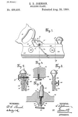
Figure 1 is a side view of my improved form of molding-plane. Fig. 2 is a cross-sectional view taken on line x x of Fig. 1. Fig. 3 is a cross-sectional view taken on line y y of Fig. 1. Fig. 4 is a sectional view taken on line z z of Fig. 1; and Fig. 5 is a sectional view taken on line v v of Fig. 1.
In constructing such a plane as the one forming the subject-matter of this application I provide a plane back or body 10, that is formed with a handle 11 and a knob 12. This body 10 is formed with a boss or projection 13, in which there is a diagonal slot adapted to receive a bit or blade, as 14. At one side of this slot I form a recess in which there is arranged a wedge-nut 15, that is engaged by a set-screw 16, said set-screw projecting through a boss 17, formed opposite the boss 13, and being held in place by a pin 18, which rides in a groove 20, that is formed in the screw 16. To the extending end of the screw 16 there is rigidly connected a thumb-piece 21. The face 2 of the nut 15 is wedge-shaped or inclined, as clearly shown in Fig. 5, so that if the screw 16 be turned to draw the nut inward the bit will be firmly clamped to place.
Along the upper portion of the plane back or body there is a rib 22, the lower face of which constitutes an abutment against which the upper edge of the formers 24 and 25 abut, said formers being each formed with under-cut grooves, adapted to receive ribs or flanges 26, that are formed upon the plane-body. The formers are held to the plane-body by set-screws 30, and are so proportioned as to closely approach each other, but so that a groove or channel of sufficient width to receive the bit 14 is left between the two formers.
From the construction described it will be seen that formers and bits of any shape desired may be secured to the plane back or body. In setting the bits they are inserted in the groove formed for their reception in the boss 13. The screw 16 is then turned so as to draw the wedge-faced clamping-nut 15 hard against the blade 14, an adjustment of the blade being obtained by advancing a screw 32, which engages with a threaded aperture that is formed in the plane-body in line with the bit-recess, this adjusting-screw being shown in Fig. 4, and its position being indicated in Fig. 1.
By means of the construction described when new forms of molding are desired, all that it is necessary to do is to provide new formers and bits, a single plane back or body with the necessary attaching devices being adapted for use in connection with any and all shapes of formers and bits.
Having thus fully described my invention, I claim as new and desire to secure by Letters Patent —
I. The combination, with a plane-body 10, of formers 24 and 25, a bit 14, an adjusting-screw 32, passed transversely through the body 10 into engagement with the inner edge of the bit, a wedge-faced clamping-bolt 15, and a screw arranged in connection with said bolt, substantially as described.
2. The combination, with a molding-plane back or body, of formers 24 and 25, formed with grooves that are adapted to receive flanges 26, which project from the plane-body parallel with its lower edge, set-screws by which the formers are clamped to the plane-body, a bit 14, which passes downward between the formers, a wedge-faced clamping-nut, an operating-screw arranged in connection with the nut, and a retaining-pin arranged in connection with the screw, substantially as described.
EDWARD D. JOHNSON.
Witnesses:
W. L. VAN HORN,
FRANK ALKIRZ.