

| PLEASE NOTE: The images presented on this page are of low resolution and, as a result, will not print out very well. If you wish to have higher resolution files then you may purchase them for only $2.95 per patent by using the "Buy Now" button below. All purchases are via PayPal. These files have all been cleaned up and digitally enhanced and are therefore suitable for printing, publication or framing. Each zip package contains all the images below (some packages may contain more), and purchased files can be downloaded immediately. |
UNITED STATES PATENT OFFICE.
_________________
GEORGE KARRMANN, OF UNIONVILLE, ASSIGNOR TO
THE UPSON NUT COMPANY, OF FARMINGTON, CONNECTICUT.
BENCH-PLANE.
_________________
SPECIFICATION forming part of Letters Patent No. 410,710, dated September 10, 1889.
Application filed May 22, 1889. Serial No. 311,692. (No model.)
_________________
To all whom it may concern:
Be it known that I, GEORGE KARRMANN, a citizen of the United States, residing at Unionville, in the county of Hartford and State of Connecticut, have invented certain new and useful Improvements in Bench-Planes, of which the following is a specification.
My invention relates to improvements in bench-planes having a device for the lateral adjustment of the cutting-bit; and the chief object of my invention is to provide a friction-slide and operating devices for moving the cutting-bit by frictional contact only.
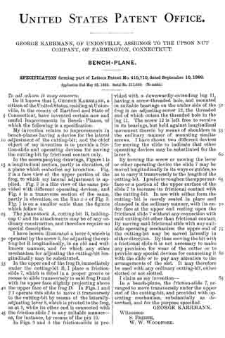
In the accompanying drawings, Figure 1 is a longitudinal section, partly in elevation, of a plane which embodies my invention. Fig. 2 is a face view of the upper portion of the frog, to which my lateral adjustment is applied. Fig. 3 is a like view of the same provided with different operating devices; and Fig. 4 is a transverse section of the same, partly in elevation, on the line x x of Fig. 3. Fig. 1 is on a smaller scale than the figures which follow it.
The plane-stock A, cutting-bit B, holding-cap C and its attachments may be of any ordinary construction, and therefore require no special description.
I have herein illustrated a lever 5, which is operated by the screw 6, for adjusting the cutting-bit B longitudinally, in an old and well-known manner, and for which any other mechanism for adjusting the cutting-bit longitudinally may be substituted.
In the upper end of the frog D, immediately under the cutting-bit B, I place a friction-slide 7, which is fitted in a proper groove or recess to slide transversely to said frog D and with its upper face slightly projecting above the upper face of the frog D. In Figs. 1 and 2 I operate this slide to move it transversely to the cutting-bit by means of the laterally-adjusting lever 8, which is pivoted to the frog, as at 9, while its other end is connected with the friction-slide 7 in any suitable manner — as, for instance, by means of the pin 10.
In Figs. 3 and 4 the friction-slide is provided with a downwardly-extending lug 11, having a screw-threaded hole, and mounted in suitable bearings on the under side of the frog is an adjusting-screw 12, the threaded end of which enters the threaded hole in the lug 11. The screw 12 is left free to revolve in its bearings, but held against longitudinal movement therein by means of shoulders in the ordinary manner of mounting similar screws. I have shown two different devices for moving the slide to indicate that other operating devices may be substituted for the lever 8.
By turning the screw or moving the lever or other operating device the slide 7 may be moved longitudinally in its ways or guides, so as to carry it transversely to the length of the cutting-bit. I prefer to roughen the upper surface or a portion of the upper surface of the slide 7 to increase its frictional contact with the cutting-bit. In use with either form the cutting-bit is merely seated in place and clamped in the ordinary manner, with its under face at the upper end resting upon the frictional slide 7 without any connection with said cutting-bit other than frictional contact. By moving said frictional slide with any suitable operating mechanism the upper end of the cutting-bit may be moved laterally in either direction. By thus moving the bit with a frictional slide it is not necessary to make any provision for wear of the cutter or to provide any special devices for connecting it with the slide or to pay any attention to the arrangements of the slot. It may therefore be used with any ordinary cutting-bit, either slotted or not slotted.
I claim as my invention —
In a bench-plane, the frictionslide 7, arranged to move transversely under the upper end of the cutting-bit, and provided with operating mechanism, substantially as described, and for the purpose specified.
GEORGE KARRMANN.
Witnesses:
S. FRISBIE,
W. W. WOODFORD.