| PLEASE NOTE: The images presented on this page are of low resolution and, as a result, will not print out very well. If you wish to have higher resolution files then you may purchase them for only $2.95 per patent by using the "Buy Now" button below. All purchases are via PayPal. These files have all been cleaned up and digitally enhanced and are therefore suitable for printing, publication or framing. Each zip package contains all the images below (some packages may contain more), and purchased files can be downloaded immediately. |
UNITED STATES PATENT OFFICE.
_________________
GEORGE D. MOSHER, OF BIRMINGHAM, CONNECTICUT, ASSIGNOR TO
THE BIRMINGHAM PLANE COMPANY, OF SAME PLACE.
PLANE.
_________________
SPECIFICATION forming part of Letters Patent No. 413,300, dated October 22, 1889.
Application filed June 25, 1889. Serial No. 315,506. (No model.)
_________________
To all whom it may concern:
Be it known that I, GEORGE D. MOSHER, a citizen of the United States, residing at Birmingham, in the county of New Haven and State of Connecticut, have invented certain new and useful Improvements in Planes; and I do hereby declare the following to be a full, clear, and exact description of the invention, such as will enable others skilled in the art to which it appertains to make and use the same.
My invention relates to certain new and useful improvements in planes, but more particularly to means for the adjustment of the cutting-bit; and the object of my invention is to furnish a device which shall be simple in construction and cheap to manufacture, and whereby a limited adjustment either longitudinally or laterally may be imparted to the bit; and with these ends in view my invention consists in the details of construction and combination of co-operating elements hereinafter to be fully set set forth, and then recited in the claims, which are hereunto annexed.
In order that those skilled in the art to which my invention appertains may fully understand its construction and method of op-
eration, I will describe the same in detail, reference being had to the accompanying drawings, which form a part of this specification, and in which —
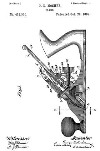
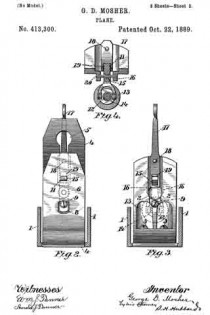
Figure 1 is a central longitudinal section through the operative parts of a plane constructed in accordance with my invention; Fig. 2, a section through the plane-stock at the line y y of Fig.1, looking in the direction of the arrow, the plane-bit being shown in front elevation and the fastening-wedge being removed; Fig. 3, a similar view, but with the wedge and bit both removed; and Fig. 4, a detail section at line x x of Fig. 1, looking toward the rear of the plane.
Like numerals denote the same parts in all the figures of the drawings.
1 is the plane-stock, having therein secured the frog 2 by screws 3 or other means. 4 is the cutting-bit, slotted longitudinally, as seen at 5, and adapted to lie against the inclined forward face of the frog. 6 is the cap-plate, which lies upon the bit and is secured thereto, as by a screw 7, whose head engages the surface of the bit at either side of the slot in the latter. The cap-plate has an opening 8 therein to allow of movement relative to the screw 9, which projects outwardly from the frog and serves in conjunction with the binding-wedge 10 to secure the bit and cap-plate firmly against the frog, as is common to many planes now in use. The cap-plate has also an opening 11, whose purpose will presently appear. At the rear of the frog, and projecting therefrom in substantially a horizontal plane, is a screw 12, upon which runs a nut 13, which is provided with an annular groove let near its forward end.
15 is a lever pivoted on a pin 20 between ears 16 on the frog. It is yoked at its lower end so as to loosely engage the groove in the nut. The pivot-joint is loose so that the lever may be moved lengthwise upon the pivot-pin, for the purpose presently explained. The upper end of the lever passes through the slot of the bit and enters the opening 11 in the cap, to which it is closely adapted.
17 is a lever fulcrumed at 18 to the upper end of the frog, said lever having near its lower end an elongated opening 19, through which the lever 15 passes and in which it may be moved by the screw.
In the adjustment of the bit by means of the instrumentalities hereinbefore described the longitudinal movement is imparted thereto by moving the nut on the screw, whereby the lever is turned upon its fulcrum and the cap and bit are carried along by means of it. The lateral movement of the bit for squaring its edge with the plane mouth is effected by the lever 17, which, being swung upon its fulcrum, will carry the lever 15 along upon the pin on which it is pivoted and thereby, through said lever, move the bit laterally. To avoid lost motion, the end of the lever 15 should conform closely to the opening in the cap-plate, in which case a very nice adjustment of the bit in both directions may be made.
As the bit wears away, the cap-plate can be moved relatively thereto, so that the lever-opening in the cap may be always in proper relative position toward the lever.
I claim —
1. In a plane of the character described, the combination, with the bit and the cap-plate, of the screw-operated lever, whose end engages the cap-plate, and the laterally-adjusting lever engaging and adapted to move the screw-operated lever and therethrough the bit, substantially as set forth.
2. In a plane, the combination the bit and the perforated cap-plate thereon secured, of the yoked and screw-operated lever pivoted to the frog and movable longitudinally of its bearing and the pivoted laterally-adjusting lever arranged around and adapted to actuate the screw-operated lever, substantially as specified.
3. The combination, in a plane, with the stock and the frog of the slotted bit, of the cap-plate having the opening 11, means, as the wedge, for securing the bit and plate to the frog, the lever 15, engaged and operated by the nut 13 and projecting into the opening 11 in the cap-plate, and the laterally-adjusting lever 17, fulcrnlned to the frog and engaging the lever 15, whereby said lever 15 may be moved along its fulcrurn, substantially as specified.
In testimony whereof I affix my signature in presence of two witnesses.
GEORGE D. MOSHER.
Witnesses:
WALTER S. TORRANCE,
EDWIN B. GAGER.


