| PLEASE NOTE: The images presented on this page are of low resolution and, as a result, will not print out very well. If you wish to have higher resolution files then you may purchase them for only $2.95 per patent by using the "Buy Now" button below. All purchases are via PayPal. These files have all been cleaned up and digitally enhanced and are therefore suitable for printing, publication or framing. Each zip package contains all the images below (some packages may contain more), and purchased files can be downloaded immediately. |
UNITED STATES PATENT OFFICE.
_________________
SOLON R. RUST, OF NEW HARTFORD, ASSIGNOR TO THE BIRMINGHAM
PLANE MANUFACTURING COMPANY, OF BIRMINGHAM, CONNECTICUT.
PLANE.
_________________
SPECIFICATION forming part of Letters Patent No. 413,329, dated October 22, 1889.
Application filed June 25, 1888. Serial No. 315,458. (No model.)
_________________
To all whom it may concern:
Be it known that I, SOLON R. RUST, a citizen of the United States, residing at New Hartford, in the county of Litchfield and State of Connecticut, have invented certain new and useful Improvements in Planes; and I do hereby declare the following to be a full, clear, and exact description of the invention, such as will enable others skilled in the art to which it appertains to make and use the same.
My invention relates to certain new and useful improvements in planes, and has for its object to provide a construction which shall be simple and easy of operation, and whereby a limited adjustment of the cutting-bit relative to the mouth of the plane may be readily effected; and with these ends in view my invention consists in the details of construction and combination of elements hereinafter fully and in detail explained, and then recited in the claims.
In order that those skilled in the art to which my invention appertains may fully understand its construction and operation, I will describe the same in detail, reference being had io the accompanying drawings, which form a part of this specification, and in which —
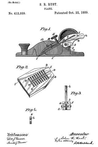
Figure 1 is a central vertical longitudinal section through a plane constructed in accordance with my invention; Fig. 2, a detail perspective showing the method of grooving the under surface of the plane-bit; Fig. 3, a detail plan view showing the adusting-lever mounted in its fulcrum-block; Fig. 4, a detail vertical section through the forward end of the lever and the opening through which the pivot passes.
Like numerals denote the same parts in all the figures of the drawings.
1 is the plane-stock, having at its rear end a divided post 2, which supports the bit and serves as the frog. At its rear side this post has a pair of inward projections 3, whose edges are somewhat beveled. (See Fig. 3.) Between the parts of the divided post is secured a lever 4, fulcrumed upon a pin or rivet 5 passed through said post. The hole in the lever is slightly larger than the rivet, and is countersunk from either end thereof, (see detail, Fig. 4,) so that the lever may have an easy movement lengthwise of the pin without binding upon the latter. At the top surface of its forward end the lever is provided with a series of teeth 6 — say three or four in number — arranged on an arc struck from the center of the fulcrum-pin.
7 is the bit, which, upon its back and for a portion of its length, is provided with a series of square-edged transverse grooves 8, spaced to correspond with the spacing of the teeth 6 upon the lever. 9 is a square-edged groove cut lengthwise of the back of the bit and centrally intersecting the transverse grooves heretofore referred to at right angles. The depth of this groove is about half that of the transverse groove, so that a sort of rack is left at the bottom of said longitudinal groove, while at the same time square abutments are left at its sides for the purpose presently explained.
10 is the wedge, having a binding-screw 11 and a flat spring 12 at its under side, against which the end of the screw abuts, so that it may not mar the upper surface of the bit when turned downward to secure it. The wedge binds the bit to the post by the ordinary rneans of a transverse rod 13, extended between the sides of the stock, and underneath which the wedge lies.
When the parts are assembled, as shown at Fig. 1, the operation of my invention is as follows: The teeth upon the lever lie in the longitudinal groove and engage with the transverse grooves which form the rack at the bottom of said groove. It will be readily understood that a limited longitudinal movement either forward or backward may be imparted to the bit by raising or lowering the handle end of the lever, the teeth of which actuate the bit by their engagement with the rack. When a lateral adjustment is desired for the purpose of squaring the cutting-edge of the bit with the plane-mouth, said adjustment may be obtained by a lateral movement of the handle end of the lever. When this is done, the sides of the teeth engage with the square abutments at sides of the longitudinal groove, and, as the lever is pivoted loosely on its pin and may move lengthwise thereon, said lever, for the purpose of this sidewise movement, fulcrums between the edges of the inward projections at the rear of the divided post and slides longitudinally upon the pin.
I claim —
1. In a plane, the combination, with the stock and the doubly-fulcrumed lever, of the cutting-bit having at its rear side the transversely-extended grooves and the shallow longitudinal groove intersecting the transverse grooves at right angles, substantially as set forth.
2. In a plane, the combination, with the cutting-bit, the same having the transverse grooves and the longitudinal groove, whereby a bearing is afforded for its actuation longitudinally and laterally, of the lever having thereon the operating-teeth and two fulcrum-points, one for the operation of the bit longitudinally and the other for its adjustment laterally, substantially as specified.
3. In a plane, the combination, with the bit, the same having the transverse and longitudinal grooves in its rear side, of the divided post, upon which said bit rests, the toothed lever loosely pivoted on a pin within said divided post, and adapted, in addition to its movement upon said pin as a center, to have a movement longitudinally thereof, substantially as set forth.
4. In a plane, the combination, with the bit, having at its rear side the transverse grooves and the shallower longitudinal groove intersecting said transverse grooves at right angles, of the divided post having the beveled inward projections at its rear side, the lever provided with operating-teeth and having a countersunk pivot-hole, and the pin secured in said post and passing loosely through the hole in the lever, substantially as specified.
In testimony whereof I affix my signature in the presence of two witnesses.
SOLON R. RUST.
Witnesses:
WM. H. WILLIAMS,
MARGARET G. TORRANCE.


