
| PLEASE NOTE: The images presented on this page are of low resolution and, as a result, will not print out very well. If you wish to have higher resolution files then you may purchase them for only $2.95 per patent by using the "Buy Now" button below. All purchases are via PayPal. These files have all been cleaned up and digitally enhanced and are therefore suitable for printing, publication or framing. Each zip package contains all the images below (some packages may contain more), and purchased files can be downloaded immediately. |
UNITED STATES PATENT OFFICE.
_________________
CARL JULIUS JACOBSEN, OF BROOKLYN, NEW YORK.
WOOD-PLANE.
_________________
SPECIFICATION forming part of Letters Patent No. 420,386, dated January 28, 1890.
Application filed May 13, 1889. Serial No. 310,562. (No model.)
_________________
To all whom it may concern:
Be it known that I, CARL JULIUS JACOBSEN, a citizen of Norway, residing at Brooklyn, in the county of Kings and State of New York, have invented certain new and useful Improvements in Wood-Planes; and I do hereby declare the following to be a full, clear, and exact description of the invention, such as will enable others skilled in the art to which it appertains to make and use the same.
My invention consists of an improved adjustable throat to compensate for the widening of the throat by wear; also, of an improved construction for the escape of the shavings and arrangement of the clamp-stay for confining the plane-bit clamp, and also of an improved adjustable stop for gaging the adjustment of the bit when replaced after sharpening, as hereinafter fully described, reference being made to the accompanying drawings, in which —
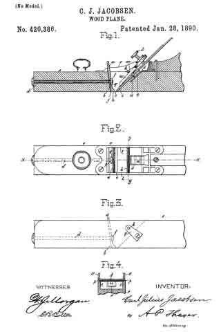
Figure 1 is longitudinal section of a portion of a plane constructed according to my improvements, the section being taken on line an x x Fig. 2. Fig. 2 is a plan view of the same with the clamp and the plane-bit omitted. Fig. 3 is a side elevation of the plane-stock, showing the arrangement of the clamp-stay in a stock not having the metallic top housing; and Fig. 4 is a transverse section on the line y y of Fig. 2.
The improvement in the throat consists of the metallic plate a, clamped onto the wall b in front of the throat c by the bolt d, extending forward through the stock e and said plate, and also through the nut f in the recess g of the throat-plate, into which nut said bolt screws by turning it by the head, the nut being held in the recess g so as not to turn, and the said plate having the lower edge h dressed to the plane of the bottom of the plane-stock, so that as the bottom of the plane-stock wears away in use and the throat-opening of the stock widens between the sloping sides of the front and back the plate may be packed out toward the edge of the plane-bit i from time to time by liners j of thin material.
The hole through the plate a for the bolt d is elongated somewhat vertically to allow the plate to shift upward as the bottom of the stock wears faster than the foot of the plate. Said foot is made a little wider than the rest above to insure clearance of the shaving from the projecting nut and end of the rod above, and also to provide a suitable breadth of the surface of the foot having contact with the work. I make the opening from the throat upward to receive the plane-bit i and clamp w and for the escape of the shavings in uniform width and with parallel sides l from the throat up for the better discharge of the shavings, and insert the clamp-stay rod k across said opening and through the sides l, which is much less obstructive to the escape of the shavings than the ribs projecting from the sides l in the common arrangement and making a contracting passage along up the clamp. The rod is also a better fulcrum for the clamp than the ribs. It is much cheaper to make, and by the application of the stop-shoulders m to the upper side of the clamp it forms a stop to control the clamp w as to its position in the opening and relatively to the plane-bit.
The clamp w drops to its position without care or trouble, and is then made tight by the adjusting-screw n in the upper end, being screwed against the plane-bit.
When the plane-stock is fitted with the metallic housing o on the top, I arrange rod k at the joint between the top of the stock and the bottom of the housing, preferably notching the lower edges of the housing to receive half the thickness of the rod, and notching the upper edges of sides l of the stock about half their thickness for receiving the other half of the end portions of the rod, and reducing the ends of the rod to overlap the rest of the thickness of sides l, as shown at p, for a simple method of fitting the rod and providing shoulders to prevent the rod from shifting out of place lengthwise.
When the stock is made without the top housing, the stay-rod will be inserted through the walls l below the top with inlaid metallic reenforcing plates q to prevent the stress of the clamp from jarring the rod slack, as it would if held in the wood only.
To gage the plane-bit so that it will lodge in the right position and same projection of the edge below when returned after being sharpened as before removal, and so as not to require readjustment, I provide the shifting stop-gage block u in the groove s for the head of the screw t, by which the double bit is clamped together, which forms a stop by which the edge of the plane is properly adjusted merely by dropping into the stock and allowing the screw-head to reach and lodge on said block. The groove s is dovetail in form, and the gage-block is fitted so as to keep its place by friction, but to allow of being shifted along slightly from time to time by the force of the clamp-screw t on it when the plane-bit is driven farther down as it wears short in sharpening it. The gage-block being set in the upper part of the groove to begin with, needs no further attention until the worn out plane-bit is replaced by a new one, when it has to be shifted upward along the groove again.
I claim as my invention —
1. The combination, with a wood-plane having the front wall of the opening above the throat inclined reversely to the inclination of the rear wall, of the adjustable throat-plate consisting of the plain flat plate adapted to be clamped on the said front wall and the clamping-bolt extending through the stock from the front end and securing the plate by the nut located in the recess of the plate, substantially as described.
2. The combination, with the plane-stock having the front wall of the opening above the throat inclined reversely to the inclination of the back wall, of the plain flat plate having the recess for the nut and slot-hole for the bolt and the clamping-bolt extending through the plane-stock from the front and securing said plate by the nut, substantially as described.
3. The combination, with the plane-stock having the sides of the opening above the throat parallel and with the bit-clamp, of the clamp-stay rod extending across the opening from side to side and secured in the bearing-notches in the joint between the top of the wood stock and the bottom of the metallic housing, substantially as described.
4. The combination, with the plane-stock having the sides of the opening above the throat parallel and with the bit-clamp, of the clamp-stay rod extending across the opening from side to side and secured in the bearing-notches and between the shoulders in the joint between the top of the wood stock and the bottom of the metallic housing, substantially as described.
5. The combination, with the plane-stock having the groove for the head of the clamp-screw and with said screw, of the adjustable step-gage block in said groove.
In testimony whereof I affix my signature in presence of two witnesses.
CARL JULIUS JACOBSEN.
Witnesses:
W. J. MORGAN,
W. P. EARLL.