
| PLEASE NOTE: The images presented on this page are of low resolution and, as a result, will not print out very well. If you wish to have higher resolution files then you may purchase them for only $2.95 per patent by using the "Buy Now" button below. All purchases are via PayPal. These files have all been cleaned up and digitally enhanced and are therefore suitable for printing, publication or framing. Each zip package contains all the images below (some packages may contain more), and purchased files can be downloaded immediately. |
UNITED STATES PATENT OFFICE.
_________________
OLE O. SKATTEBO, OF HANNAFORD, NORTH DAKOTA,
ASSIGNOR OF ONE-HALF TO JORGEN HANSON, OF SAME PLACE.
PLANE.
_________________
SPECIFICATION forming part of Letters Patent No. 434,361, dated August 12, 1890.
Application filed March 8, 1890. Serial No. 343,098. (No model.)
_________________
To all whom it may concern:
Be it known that I, OLE O. SKATTEBO, of Hannaford, in the county of Griggs and State of North Dakota, have invented a new and Improved Plane, of which the following is a full, clear, and exact description.
My invention relates to improvements in carpenters’ planes; and the object of my invention is to provide a plane that will be equally efficient as a square or bevel plane, and that may be readily converted from one to the other, and also to provide a plane in which a great variety of tools may be inserted, so that the plane maybe used for matching, rabbeting, grooving, rounding, beading, and the like.
To this end my invention consists in a plane constructed substantially as hereinafter described and claimed.
Reference is to be had to the accompanying drawings, forming a part of this specification, in which similar letters of reference indicate corresponding parts in all the figures.
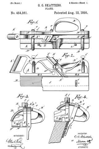
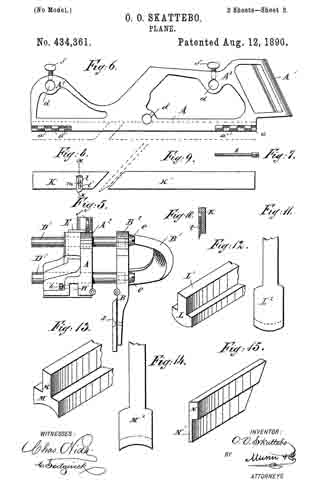
Figure 1 is a plan view of the plane; Fig. 2, a side elevation of the same with a portion of the guide-plate broken away; Fig. 3, an end view of the device as adjusted for a square plane, but with the guide-strip removed; Fig. 4, an end view of the same adjusted for a bevel-plane; Fig. 5, an end view of the plane adjusted for rabbet-work; Fig. 6, a side elevation of one of the separable parts of the plane with a portion of one hinge in section; Fig. 7, a detailed view of the pintle of the plane-hinges; Figs. 8 and 9, side elevations of the strips used for matching and rabbeting; Fig. 10, a transverse section on the line x x, of Fig. 8; Fig. 11, a detail view in elevation of the grooving-knife; Fig. 12, a perspective view of the grooving-guide; Fig. 13, a perspective view of the rounding or molding guide; Fig. 14, a front elevation of a corresponding knife for same, and Fig. 15 a perspective view of a ripping-guide.
The body or frame of the plane consists of two longitudinally-separable parts A and B, which are so hinged together by hinges a, near the ends thereof, that they may be placed at various angles with each other. The hinges a are attached to the inner edge of the part A, which carries the planer-knives, and to the upper edge of the part B, so that when the parts are shut closely together, the part B will shut against theinner edge of the part A, so as to project downwardly at right angles with the same. The hinges a are also provided with a removable pintle b, which fits in the knuckles a’ of the hinges, and which is screw-threaded at the end to engage a similar thread upon the interior of the inner knuckle of the hinges, so that the pintle may be easily removed and the parts A and B of the frame separated.
The parts A and B are each provided with a suitable handle A’ B’, by which the plane may be pushed or pulled, as the case may be, and with upwardly-extending braces A2 and B2, which fit closely together, and which are provided with corresponding holes d, through which extend the curved arms D or straight arms D’, said arms being attached to the braces B2 by the screws e, which fit a screw-thread in the ends of said arms, and being retained in the braces A2 by the binding-screws f which project through from the top of said braces and impinge upon said arms, so that the parts A and B are adjustably connected by the arms D and D’ and their attaching-screws.
In order that there may be no movement whatever between the parts A and B when adjusted by the straight bars, I provide other openings d’ below and between the upper openings d, one of said openings d’ being shown in Fig. 2 and 5. The lower bar D’ passes through said opening d’.
The part A of the frame is provided with the usual slide E, in which a knife F is inserted, with a set-screw g, which projects through the slide and holds the knife in position therein, and with a slot E’, through which the knife extends below the bottom of the plane. The part A is also provided upon the bottom with a longitudinal groove or recess H, which extends the entire length thereof, in which the various guides are inserted, as hereinafter described, and with screws h, which project through the wall of said groove, by means of which the guides are retained in the groove.
Attached to the inner side of the part B is the vertically-adjustable guide-plate J, which is of the same length as the part B and extends below the lower edge thereof. It serves as a guide to the plane, and is attached to the part B of the frame by the screws i, which project through vertical slots j in the plate into the side of the part B, so that by loosening said screws the plate may be easily adjusted upon the frame.
When a square edge is to be planed, the parts A and B of the frame are locked together, so that they will be at right angles with each other, as best shown in Fig. 3, and the plane is used as an ordinary square-edge plane. When a beveled edge is to be planed, the curved arms D are inserted in the holes d, and the parts are swung apart upon their hinges till the desired bevel is obtained, when they are retained in this position by tightening the binding-screws f upon the arms D. This position is best shown in Fig. 4. The plane is then used as an ordinary bevel-plane. To facilitate the adjustment to any bevel, the curved arms D should be marked off into degrees, and then when the proper degree is indicated upon the arms they may be secured in position as desired.
If the plane is to be used as a matching-plane, the guide-strips K and K’, which are of about the width of the groove to be planed, are inserted in the groove H in front of and behind the slot E’. A suitable narrow knife is inserted in the slide E so as to project down between the guide-strips K and K’, and the plane is used as an ordinary matching-plane. If a tongue is to be cut, the guide-strips K and K’ are removed and a suitable knife for tongue-planing inserted in the slide E.
If the plane is to be used as a rabbet-plane, the curved arms are removed from the holes d and the straight arms D’ inserted, the pintle b is removed from the hinges a, and the plane will then be laterally adjustable. The arms D’ are held in a desired position by the binding-screws f in the same way that the arms D are secured, and the arms should be marked off into fractions of an inch, that they may be easily adjusted. The guide-strip K’ and the guide-strip K, which is provided with a vertically-adjustable knife l, which is attached thereto by a screw m, projecting through a slot l’ thereof, are inserted in the groove H and held by the screws h. A suitable knife is inserted in the slide E, and the plane is ready for rabbet-work. In using it as a rabbet-plane and for other similar work the distance of the knife from the edge of the board is regulated by the arms D’ and binding-screws f as the part B of the frame, which extends down the side of the board, may be brought as near to the part A as desired, and is secured in that position, as described. When used for rabbet-work, the knife l will project a desired distance below the guide-strip K, and, entering the board to be planed, will cut a smooth surface for the shoulder of the rabbet.
In Figs. 11 and 12 I have shown a knife and guide for grooving. The guide L is provided with an upwardly-projecting tongue L’, which fits into the groove H of the plane, is held therein by the screws h, and is provided with a rounding lower face corresponding with the groove to be planed. The knife L2 has a convex edge corresponding to the shape of the lower surface of the guide L. It is inserted in the slide E of the plane in the usual manner, and the plane is used as an ordinary grooving-plane.
In Figs. 13 and 14 I have shown a knife and guide for rounding or molding. The guide M is provided with a tongue M’ which fits the groove H, and which is used in the same way as the grooving-guide. The rounding-guide, however, is provided with a concave lower surface and the plane with a corresponding knife M2, having a concave cutting-edge.
When the plane is to be used as a ripping-plane, the ripping-guide N, having a narrow edge N’, is secured in the groove H, a suitable ripping-knife is inserted in the slide E, and the plane is used as a ripping-plane.
I might show many more tools that could be used with the plane; but without going further into details it is evident that by making a suitable guide to fit the groove H and providing a corresponding knife the plane may be used to produce almost any form.
It will be seen from the foregoing description that a person by having a plane as described, with the accompanying guides and knives, can do the work now performed by a great many separate planes.
Having thus described my invention, what I claim as new, and desire to secure by Letters Patent, is —
1. A plane consisting in a stock or knife-carrying portion, a longitudinal guide adapted to be held parallel with or at any desired angle to the said stock, a separable hinge-joint to connect the two parts when the guide is to be held at an angle, and interchangeable rods and set-screws for holding the guide parallel with or at an angle to said stock, substantially as set forth.
2. A plane consisting, essentially, of two longitudinally-separable parts, the knife-carrying part having a longitudinal slot in the bottom thereof, in which any desired form of guide maybe inserted, and having a suitable slide in which a knife may be secured to match said guide, substantially as described.
3. The combination, with the plane A B, the part A having a longitudinal groove in the bottom thereof, as shown, of the rabbet-guide K, adapted to fit in said groove, and having a vertically-adjustable knife l affixed thereto to cut the shoulder of the rabbet, substantially as described.
OLE O. SKATTEBO.
Witnesses:
MARTIN MOSSING,
ERIK AUSTAD.