
| PLEASE NOTE: The images presented on this page are of low resolution and, as a result, will not print out very well. If you wish to have higher resolution files then you may purchase them for only $2.95 per patent by using the "Buy Now" button below. All purchases are via PayPal. These files have all been cleaned up and digitally enhanced and are therefore suitable for printing, publication or framing. Each zip package contains all the images below (some packages may contain more), and purchased files can be downloaded immediately. |
UNITED STATES PATENT OFFICE.
_________________
ARTHUR E. RUST, OF PINE MEADOW, CONNECTICUT,
ASSIGNOR OF ONE-HALF TO SOLON R. RUST, OF SAME PLACE.
BENCH-PLANE.
_________________
SPECIFICATION forming part of Letters Patent No. 435,951, dated September 9, 1890.
Application filed July 29, 1889. Serial No. 319,130. (No model.)
_________________
To all whom it may concern:
Be it known that I, ARTHUR E. RUST, a citizen of the United States, residing at Pine Meadow, in the county of Litchfield and State of Connecticut, have invented certain new and useful Improvements in Bench-Planes; and I do hereby declare the following to be a full, clear, and exact description of the invention, such as will enable others skilled in the art to which it appertains to make and use the same.
My invention relates to improvements in bench-planes in which the bit is adjusted by means of a lever; and the objects of my improvement are, first, to provide a means of adjusting the bit of a bench-plane longitudinally, making it cut the thickness desired, and, second, to adjust the bit laterally, thus squaring the cutting-edge of the bit with the face of the plane. Both objects are attained by the movement of one lever either longitudinally or laterally, each motion being independent of the other, as illustrated in the accompanying drawings, in which —
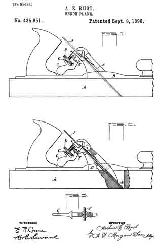
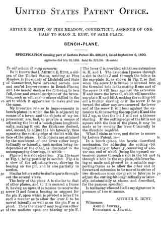
Figure 1 is a side elevation. Fig. 2 is same as Fig. 1, being partially in section. Fig. 3 is a view of the adjusting-lever, showing its bearing on the pin, and is also partially in section.
Similar letters refer to similar parts throughout the several views.
The body of the plane A is similar to that of other planes, and to it is secured a frame B, having an upward extension to receive the screw D and form a bearing or support for the pin F, upon which is pivoted a lever C in such a manner as to allow the lever C to he moved laterally as well as on the pin F as a pivot. Thus the lever C may be given either of two motions upon one bearing or pin F. The lever C is provided with three extensions G, H, and I. The extension I passes through a slot in the bit J and through the hole a in the cap-plate K, as shown in Fig. 2, so that when the screw D is turned or screwed into the threaded hole in the casting B one end of the screw D will bear against the extension H and move the lever C, which will move the cap-plate K and bit J, making the cutting-bit cut a thicker shaving, or if the screw D be turned the other way or unscrewed the lower end of the screw D will bear against the extension G, thus moving the cap-plate K and the bit J up, so that the bit J will cut a thinner shaving. If the cutting-edge of the bit is not square with the face of the plane, it may be made so by moving the lever C laterally in the direction required.
What I claim as new, and desire to secure by Letters Patent, is —
In a bench-plane, the herein-described mechanism for adjusting the cutting-bit longitudinally or laterally, consisting of a lever one end of which (being the upward extension) passes through a slot in the bit and through a hole in the cap-plate, this lever being so made and pivoted in a suitable supporting-frame as to allow the other end or downward extension to be moved in either of two directions upon one pivot or fulcrum to adjust the cutting-bit longitudinally or laterally, substantially as shown and described, for the purpose specified.
In testimony whereof I affix my signature in presence of two witnesses.
ARTHUR E. RUST.
Witnesses:
AMIE S. JEWELL,
FREDERICK A. JEWELL.