
| PLEASE NOTE: The images presented on this page are of low resolution and, as a result, will not print out very well. If you wish to have higher resolution files then you may purchase them for only $2.95 per patent by using the "Buy Now" button below. All purchases are via PayPal. These files have all been cleaned up and digitally enhanced and are therefore suitable for printing, publication or framing. Each zip package contains all the images below (some packages may contain more), and purchased files can be downloaded immediately. |
UNITED STATES PATENT OFFICE.
_________________
OLIVER LONGVAL, OF MILLBURY, MASSACHUSETTS.
CARPENTER’S PLANE.
_________________
SPECIFICATION forming part of Letters Patent No. 444,897, dated January 20, 1891.
Application filed April 5, 1889. Serial No. 306,093. (No model.)
_________________
To all whom it may concern:
Be it known that I, OLIVER LONGVAL, of Millbury, in the county of Worcester and State of Massachusetts, have invented certain new and useful Improvements in Carpenters’ Planes; and I do hereby declare that the following is a full, clear, and exact description thereof, reference being had to the accompanying drawings, forming a part of this specification, and in which —
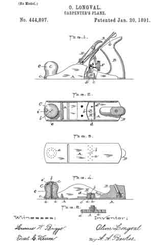
Figure 1 represents a side view, partly in section, of a carpenters plane embodying my improvements. Fig. 2 is a horizontal section through the handle, showing a plan of the plane with all the old detachable parts removed to more fully illustrate my improvement. Fig. 3 is a plan of the bottom of the plane. Fig. 4 is a central vertical longitudinal section through the parts shown in Fig. 2, and Fig. 5 is an enlarged view showing a vertical section through a part of the plane-bed.
My invention relates more particularly to metal planes, but is also applicable to other styles of planes; and it consists in combining with the plane-bed oiling devices for supplying the bottom thereof with a proper amount of oil or other lubricating material to render the operation of planing more easy to perform, as hereinafter more fully set forth.
In order that others may better understand the nature and purpose of my said invention, I will now proceed to describe it more in detail.
In the drawings, the part A represents the bed of the plane, designed to be made of metal in the class of planes shown.
B is the main rear handle, and C the front-handle.
D is the blade or knife, E the holding-cap, and F and G the thumb-screw and lever, respectively, for adjusting said blade or knife.
As my invention relates only to the oiling devices, previously referred to, of the plane, it will be unnecessary to give a detailed description of said old parts.
I accomplish the desired result — viz., of oiling the bottom of the plane and the surface of the stock operated upon — by combining an oil-receptacle H with the bed of said plane back of the knife and other detachable parts connected therewith, and by converting the usual front handle into an oil-receptacle, the same being made hollow for the purpose, as is shown in Fig. 4. The oil is allowed to pass out of said receptacles for the above purpose through suitable openings a, made in the plane-bed A. The receptacles are filled with cotton waste or other suitable material saturated with oil, as is common in other oil-receptacles, and consist of the inverted detachable cups d e, which are provided with suitable plugged inlets d’ e’ for supplying the oil thereto, and having the screws b passed vertically through the same into the bed A for holding them in position.
The detachable cups d e of the oil-cups are made oil as well as air tight where they connect with the plane-bed, as well as where the holding-screws b thereof pass through, by means of suitable elastic washers or “packings” c. The motion of the plane over the surface being operated upon produces just sufficient suction to draw out the required amount of oil to produce the desired result, and the discharge thereof is facilitated by making the discharge-openings tunnel-shaped or flaring upward, as is best shown in Fig. 5. Said form of openings also obviates the liability to their becoming clogged or stopped by dust and other particles entering and becoming lodged therein. As above constructed, such particles, if they enter, are allowed to pass up and spread out into the oil, and therefore do not materially interrupt the outflow of said oil. Although it is preferable in practice to thus form the openings a, I do not limit myself thereto, but reserve the right to employ such shapes as are suitable for the purpose.
I am aware of the United States Patents to W. Wood, No. 191,393, dated May 29, 1877; E. F. Gordon, No. 213,104, dated March 11, 1879, and to L. A. Dearth, No. 363,213, dated May 17, 1887, and make no claim to any of the constructions therein set forth.
Having now fully described my invention, what I claim therein as new, and desire to secure by Letters Patent, is —
In a carpenter’s plane, the combination, with the plane-bed A, having a series of vertical openings a, therein, of detachable cups d and e, having suitable plugged inlets d’ e’ and fitted over said openings a, in the bed, the fastening-screws b, passed vertically through the oil-receptacles into the bed, the absorbent material contained within the oil-receptacles, and the packings c, interposed between the under side of the heads of the fastening-screws and the oil-receptacles and between said oil-receptacles and the top of the bed, substantially as and for the purpose set forth.
OLIVER LONGVAL.
Witnesses:
A. A. BARKER,
W. B NOURSE.