
| PLEASE NOTE: The images presented on this page are of low resolution and, as a result, will not print out very well. If you wish to have higher resolution files then you may purchase them for only $2.95 per patent by using the "Buy Now" button below. All purchases are via PayPal. These files have all been cleaned up and digitally enhanced and are therefore suitable for printing, publication or framing. Each zip package contains all the images below (some packages may contain more), and purchased files can be downloaded immediately. |
UNITED STATES PATENT OFFICE.
_________________
GRANVILLE W. WRIGHT, OF NEW HAVEN, CONNECTICUT,
ASSIGNOR TO SARGENT & COMPANY, OF SAME PLACE.
PLANE.
_________________
SPECIFICATION forming part of Letters Patent No. 445,793, dated February 3, 1891.
Application filed October 6, 1890. Serial No. 367,226. (No model.)
_________________
To all whom it may concern:
Be it known that I, GRANVILLE W. WRIGHT, of New Haven, in the county of New Haven and State of Connecticut, have invented a new Improvement in Planes, (B;) and I do hereby declare the following, when taken in connection with accompanying drawings and the letters of reference marked thereon, to be a full, clear, and enact description of the same, and which said drawings constitute part of this specification, and represent, in —
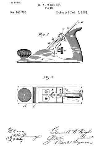
Figure 1, a side view of the plane complete, a portion being broken away to illustrate the invention; Fig. 2, a top view of the same with the plane-iron removed.
This invention relates to an improvement in that class of planes in which the stock is made from metal, the stock being constructed with a seat upon which the plane-iron may rest, and provided with mechanism for clamping the iron upon the seat, and in which provision is made for adjusting the upper end of the plane-iron laterally in order to change the line of the cutting-edge of the plane-iron with relation to the face of the stock; and the invention particularly relates to the mechanism for making such lateral adjustment; and it consists in the construction, as hereinafter described and particularly recited in the claim.
A represents the stock, made from cast metal; B, the seat upon which the plane-iron rests; C, the throat through which the edge of the iron projects; D, the plane-iron; E, the clamp by which the plane-iron is secured, and F the adjusting-screw by which the plane-iron is adjusted up and down to decrease or increase the extent of cut. So far the plane is of common and well-known construction, and does not require particular description. The upper end of the seat B, on which the plane-iron rests, is recessed, and in the recess a lever G is arranged to lie directly behind the plane-iron, and swing transversely in a plane parallel with the plane-iron. On the seat is a stationary stud H, which forms the pivot for the lever G, the lever G being forked at its lower end to embrace the stud. Above the stud H in the bed a transverse slot I is formed. In the lever a stud J is fixed or made as a part of the lever, projecting from the face of the lever toward the plane-iron, the diameter or width of this stud corresponding to the width of the vertical slot in the plane-iron and so as to extend into that slot, as seen in Fig. 1. On the reverse side of the lever G is a like projection or stud K, which works in the transverse slot I, and so that as the lever swings to the right or left the said stud J will move with it, the stud J forming a guide or holder for the lever to retain it in place, the stud preferably having a head upon the under side of the slot I, as seen in Fig.1, so as to prevent accidental detachment of the lever from the stock. When the plane-iron is introduced, its slot passes over the stud J, and so that the stud J will stand within that slot, and when the plane-iron is secured in place if it be desired to adjust the line of the cutting-edge with relation to the face-plate the lever G is turned accordingly to the right or left, as the case may be, and as indicated in broken lines, Fig. 2, such movement of the lever throwing the upper end of the plane outward to the right or left, and correspondingly changing the angle of the edge of the plane-iron with relation to the face of the stock. Preferably the lever extends above the upper end of the plane-iron, so as to form a thumb-piece L, for the convenient adjustment of the handle; but this is not essential to the invention.
I do not wish to be understood as claiming, broadly, a plane having the lever arranged to swing transversely and in engagement directly or indirectly with the plane-iron, whereby the upper end of the plane-iron is transversely adjusted according to the swinging of said lever and the angle of the edge of the plane-iron thereby adjusted with relation to the face of the plane, as such, I am aware, is not new; but
What I do claim is —
In a plane in which the stock is constructed with a seat B, upon which the plane-iron D may rest and be secured, the seat provided with a stationary stud H, and constructed with a transverse slot I above said stud, combined with a lever G, hung upon said fixed stud and extending upward in a plane substantially parallel to the plane of the plane-iron, the said lever constructed with a stud J, corresponding to the slot of the plane-iron, and also with an stud K, extending into and so as to move in said transverse slot I, all substantially as and for the purpose described.
In testimony whereof I have signed this specification in the presence of two subscribing witnesses.
GRANVILLE W. WRIGHT.
Witnesses:
E. H. EGGLESTON,
W. S. COOKE.