
| PLEASE NOTE: The images presented on this page are of low resolution and, as a result, will not print out very well. If you wish to have higher resolution files then you may purchase them for only $2.95 per patent by using the "Buy Now" button below. All purchases are via PayPal. These files have all been cleaned up and digitally enhanced and are therefore suitable for printing, publication or framing. Each zip package contains all the images below (some packages may contain more), and purchased files can be downloaded immediately. |
UNITED STATES PATENT OFFICE.
_________________
JACOB SIEGLEY, OF WILKES-BARRE, PENNSYLVANIA.
BENCH-PLANE.
_________________
SPECIFICATON forming part of Letters Patent No. 446,194, dated February 10, 1891.
Application filed May 23, 1890. Serial No. 352,944. (No model.)
_________________
To all whom it may concern:
Be it known that I, JACOB SIEGLEY, of Wilkes-Barre, in the county of Luzerne and State of Pennsylvania, a citizen of the United States, have invented certain new and useful Improvements in Bench-Planes, of which the following is a specidcation.
This invention relates to certain improvements in the bench-plane for which Letters Patent No. 294,919 were granted to me heretofore under date of March 11, 1884, said improvements being designed with a view to simplify the adjustment and the clamping of the cutting tool or bit to the stock and to perrmit the quick and convenient adjustment of the bit.
The invention consists of a bench-plane in which the cutting tool or bit is rigidly fastened to the stock by a clamping-block having transverse steel edges that are pressed against the bit by a thumb-screw acting on the top of the block. The steel block is provided with a longitudinal top groove and guided by said groove on a fixed steel plate attached to the stock, so as to permit the adjustment of the clamping-block by a threaded shank turning in recesses of the stock and by a nut located in an opening of the stock, as will be more fully described hereinafter, and finally pointed out in the claims.
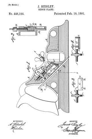
In the accompanying drawings, Figure 1 represents a side elevation of my improved bench-plane. Fig. 2 is a vertical transverse section on the line 1 1, Fig. 1; and Figs. 3 and 4 are respectively a side elevation and a top view of the steel block for clamping the bit of the plane, said block and its adjusting screw-nut being drawn as detached from the stock.
Similar letters of reference indicate corresponding parts.
Referring to the drawings, A represents the stock of my improved bench-plane, which stock is made of cast-iron or other suitable metal, and provided with a handle of the usual form at the rear end. The middle part of the stock is provided with an inclined recess a, in which the cutting tool or bit B is guided and locked in position by means of a steel block C, which is provided in its bottom facing the bit with transverse hardened-steel edges d d, that are pressed firmly against the bit by a wing-screw D, and hold it thereby securely in its place in the stock A. The top of the steel block C is provided with a longitndinal slot e, which is engaged by a steel plate e’, that is attached to the recessed side of the stock A by means of fastening-screws e2. The steel plate e’ serves for holding the steel block in position and guiding it in its up-and-down motion when it is adjusted with the bit. After the bit is adjusted the wing-screw D, which passes through the stock at right angles to the clamping-block C, is tightly applied to the block so as to clamp the same and the bit B firmly to the stock.
The steel block C is provided with a threaded shank f, which is located in recesses f’ of the stock and engaged by a screw-nut f2, having a milled rim, said screw-nut extending transversely through an opening f3 of the stock A and being retained in position therein by the adjacent portions of the stock. On turning the screw-nut f2 in one or the opposite direction the steel block C is moved up or down and carries the bit along so as to adjust the same in proper position in the stock. After the adjustment is made the wing-screw D is tightly applied to the steel block e’, so that the same clamps the bit firmly and securely in position.
My improved fastening and adjusting device for the bit permits the quick adjustment and reliable clamping of the same without necessitating the slotting or recessing of the bit for applying the adjusting device.
Having thus described my invention, I claim as new and desire to secure by Letters Patent —
1. The combination, with the stock, of a bench-plane, said stock having an inclined recess, a cutting tool or bit in said recess, a clamping-block having hardened edges bearing on said bit, and means for adjusting said steel block and bit, substantially as set forth.
2. The combination, with a stock having an inclined recess, of a cutting tool or bit seated in said recess, a clamping-block having hardened edges bearing on said bit, a wing-screw pressing on the top of the block for clamping it to the bit, and means for adjusting said block and bit, substantially as set forth.
3. The combination, with a stock having an inclined recess, of a cutting tool or bit seated in said recess, a clamping-block having hardened edges at the bottom and a longitudinal guide-groove in its top, a steel plate attached to the stock and extending into said top groove, a wing-screw pressing in the top of the block for clamping the same to the bit, and means for adjusting the steel block and bit, substantially as set forth.
4. The combination, with a stock; having an inclined recess, of a cutting tool or bit seated in said recess, a clamping-block having transverse hardened edges at its bottom and a longitudinal groove in its top part, a fixed guide-plate extending into said groove, a threaded shank attached to the clamping-block and set into recesses of the stock, and an adjusting screw-nut engaging said shank and located in an opening of the stock, substantially as set forth.
In testimony that I claim the foregoing as my invention I have signed my name in presence of two subscribing witnesses.
JACOB SIEGLEY.
Witnesses:
HENRY JACKSON,
C. W. KULP.