
| PLEASE NOTE: The images presented on this page are of low resolution and, as a result, will not print out very well. If you wish to have higher resolution files then you may purchase them for only $2.95 per patent by using the "Buy Now" button below. All purchases are via PayPal. These files have all been cleaned up and digitally enhanced and are therefore suitable for printing, publication or framing. Each zip package contains all the images below (some packages may contain more), and purchased files can be downloaded immediately. |
UNITED STATES PATENT OFFICE.
_________________
JOHN F. MAGNUSON, OF NEW YORK, N. Y.
SPOKESHAVE.
_________________
SPECIFICATION forming part of Letters Patent No. 452,498, dated May 19, 1891.
Application filed May 29, 1890. Serial No. 353,530. (No model.)
_________________
To all whom it may concern:
Be it known that I, JOHN F. MAGNUSON, a citizen of Sweden and a resident of New York city, in the county and State of New York, have invented new and useful Improvements in Spokeshaves, of which the following is a specification.
My invention consists, essentially, in a novel contrivance of adjustable-handles adapted for holding the tool in different positions for facilitating the use of it in various different parts and shapes of the work, and it also consists in an improved construction for enabling the tool to be utilized as a corner plane and for the application and adjusting of the guard-cap of the plane bit, all as hereinafter fully described, reference being made to the accompanying drawings, in which —
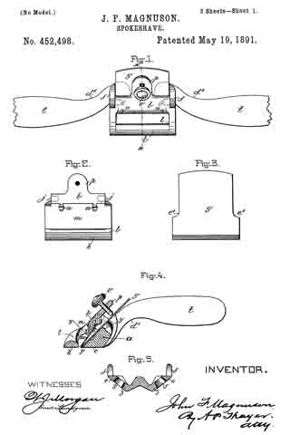
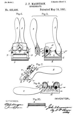
Figure 1 is a plan view of the tool with the handles adjusted about as in the ordinary spokeshave. Fig. 2 is an inside elevation of the front part of the stock detached and reversed and with the guard-cap attached to it. Fig. 3 is an elevation of the back of the plane bit. Fig. 4 is a transverse section of the complete tool on the line x x of Fig. 1. Fig. 5 is a plan view of the tool with the handles adjusted as for a corner plane. Fig. 6 is a plan view of the tool with the handles as in Fig. 5 and inverted and with one of the handles detached to show the mode of its connection and adjustment. Fig. 7 is a side elevation of the tool with the handles adjusted as in Fig. 5. Fig. 8 is a front elevation of the back part of the stock with one of the handles detached and with the other handle in the normal position of the spokeshave-handle. Fig. 9 is a transverse section of the stock on line w w, Figs. 6, 7, and 8, and Fig. 10 is a section of the front part of the stock on line y y, Figs. 4 and 5.
I construct the stock in two parts a and b, the former being what l call the “back” and the latter the “front” part. The back has the bevel base c, the front face d, the inclined sides e, and the ear-lugs f. The base c that part which slides on the wood, the plane bit q rests on the front face d, the inclined sides e have the handles t pivoted to them, respectively, and the front part b is secured in the ear-lugs f by pivot-studs i entering its shoulders j. Said front part also has a bevel base k to slide on the wood in advance of the plane-bit, above which is a large opening l for the escape of the shavings, and above the opening, but a little below the pivots i, the guard-cap m is attached to the under or rear side by the clamp-screws n slots of the cap, so that the cap can be adjusted up or down to gage it with relation to the edge of the plane-bit, said cap bearing all across the bit slightly above said edge. The front part b has an upward extension p above the pivots i, through which the clamp-screw o is fitted to bear the plane-bit g on the face d, and at the same time bear the lower edge of the guard-cap in on the lower end of the plane-bit just above the edge of said bit by the leverage taking effect thereon through the pivots of said front part.
The outer surfaces of the bevel sides e of the back have pivot-holes s for the handles t and are faced on the margins q, surrounding said holes, and the handles are correspondingly faced at u to seat thereon and have a pivot-stud w in the center of the face u, adapted to fit the hole q and being tapped in its center to receive the fastening-screw x from the upper surface of side e and having a washer y under its head. The face q is recessed at z about a quarter of the circumference of the pivot-hole to provide two stop-shoulders a’ and b’, and the pivot-stud w has a stop-lug c’, which swings between said shoulders and comes to rest on them, respectively, to stop the handle in its different positions. When the handles are in the positions represented in Figs. 4, 5, and 6, said stop-lugs bear against shoulders a’, and when in the positions of Figs.1 and 8 they bear on the shoulders b’. The pivot-screws x and washers y are to be adjusted so as to bind the handle-pivots with sufficient friction to cause them to retain their places when set, but allow them to be shifted without difficulty.
In Figs. 4 and 7 it will be seen that the handles have an upward rise from the pivots to a sufficient height to enable the hand of the user to clear the work while holding the tool, and these are bent at d’ and project for the rest of their length about parallel with the base c k of the tool, which bends give the forward pitch of the handles, so that they range about in line with the cutting-edge of the bit when adjusted as in Figs. 1 and 8, substantially the same as in the ordinary spokeshave. Another feature of this form of the handles and the inclined sides e, to which they are pivoted, is that when shifted to the positions of Figs. 1 and 8 the handles, which are preferably about twice as wide as they are thick, assume the flatwise positions as therein shown, in which they are used separately, one in each hand, and in the positions of Figs. 5 and 6 they turn up edge-wise, side by side, and within narrower space than the width of the stock, suitably for both being grasped by one hand, in which positions the tool can be used substantially as a corner plane for both right and left hand corners, for which purpose it will be seen that the plane-bit is made as wide as the stock and is at its edges flush with the edge of the stock — a condition that is made feasible by the contrivance of the pivoted front part of the stock for clamping the bit and by making the upper part of the plane-bit narrower, as at e’, to extend upward between the ear-lugs by which the front b is pivoted, said ear-lugs being necessarily located within the width of the base c k and of the cutting-edge of the bit to permit the use of the tool in corners. It will be seen that besides this advantage the separate construction and pivoted connection of the front and back parts of the stock enables the handles to be secured by the screws inserted from the inside of the back and the guard-cap to be attached by the screws n inserted from the inside of the front in such manner that the screws have no objectional exterior projections that might interfere with or obstruct in the application of the tool to some shapes of work.
In Figs. 4 and 10 it will be seen that the lower edges of the sides of the front b are beveled downward to the edges b’, so as to make the mouth or lower side of the opening l, for the escape of the shavings as wide as the plane-bit and the whole width of the stock, so that the shavings will enter without obstruction, and so as to be forced upward between the said sides, which are of necessity convergent upward to enable the requisite quantity of material for supporting the lower part of front b to be contained in said sides.
I claim —
1. The combination of the separately-constructed back and front parts of the stock, pivoted together and provided with the clamp-screw, said back having the face for the reception of the plane-bit, and the front having the guard-cap attached to the inner side suitably for being pressed at the lower end on the plane-bit by the clamp-screw, said cap bearing all across the bit, substantially as described.
2. The combination of the separately-constructed back and front parts of the stock, pivoted together and provided with the clamp-screw, said back having the face for the reception of the plane-bit, and the front having the guard-cap, said guard-cap and plane bit having equal width and extending flush with the sides of the stock, and the plane bit having the narrower upper part extending between the ear-lugs of the pivot-joint of the two parts of the stock, substantially as described.
3. The combination, with the stock having the inclined sides, of handles pivoted to said sides, respectively, and adapted to be set in the laterally-projecting positions of spokeshave-handles and also in the rearwardly-projecting position side by side, substantially as described.
4. The combination, with the stock having the inclined sides, of the handles pivoted to said sides, respectively, and adapted to be set in the laterally-projecting positions of spokeshave-handles and also in the rearwardly-projecting position side by side and provided with stops limiting the movements to said positions, substantially as described.
5. The combination, with the stock having the inclined sides, of the handles pivoted to said sides by pivot-studs and the handles entering the pivot-holes of the sides and secured from the inside of the stock by the screws, substantially as described.
6. The combination of the separately-constructed front and back parts of the stock, detachably pivoted together and the handles pivoted to the inclined sides of the stock and secured by the screws and washers inside of the back and under the front part of the stock.
7. The combination, with the stock having the inclined sides, of the handles pivoted thereto and having the curved or angular section d’, substantially as described.
8. A spokeshave-stock made in two separate parts pivoted together and having the space for the plane-bit extending the whole width of the stock, and the front part having the opening for the escape of the shavings made the full width of said stock at the lower sides and with upwardly-converging sides, substantially as described.
9. The combination of the separately-constructed back and front parts of the stock, pivoted together and provided with the clamp-screw, and the guard-cap adjustably attached to the inner side of the front part by the slots and fastening-screws, said back part having the face for reception of the plane-bit, substantially as described.
In testimony that I claim the foregoing as my invention I have signed my name, in presence of two witnesses, this 24th day of April, 1890.
JOHN F. MAGNUSON.
Witnesses:
W. J. MORGAN,
W. B. EWELL.