
| PLEASE NOTE: The images presented on this page are of low resolution and, as a result, will not print out very well. If you wish to have higher resolution files then you may purchase them for only $2.95 per patent by using the "Buy Now" button below. All purchases are via PayPal. These files have all been cleaned up and digitally enhanced and are therefore suitable for printing, publication or framing. Each zip package contains all the images below (some packages may contain more), and purchased files can be downloaded immediately. |
UNITED STATES PATENT OFFICE.
_________________
CHARLES F. YOUNG, OF BIRMINGHAM, CONNECTICUT, ASSIGNOR TO
GEORGE D. MOSHER AND SIMON NOVITZKY, BOTH OF SAME PLACE.
BENCH-PLANE.
_________________
SPECIFICATION forming part of Letters Patent No. 455,957, dated July 14, 1891.
Application filed March 7, 1891. Serial No. 384,110. (No model.)
_________________
To all whom it may concern:
Be it known that 1, CHARLES F. YOUNG, a citizen of the United States, residing at Birmingham, in the county of New Haven and State of Connecticut, have invented certain new and useful Improvements in Bench-Planes; and I do hereby declare the following to be a full, clear, and exact description of the invention, such as will enable others skilled in the art to which it appertains to make and use the same.
This invention relates to certain novel and useful improvements in bench-planes.
It is the object of my invention to improve upon the construction of plane commonly known as the “Bailey” plane, and which is shown and described in Letters Patent No. 67,398, dated August 6, 1867, in such manner that while the bit may be freely fed and adjusted longitudinally in the seat in substantially the manner indicated in said patent to Bailey said bit may also be adjusted laterally for the purpose of squaring its edge with the plane-mouth; and with these ends in view my invention consists in the construction and combination of elements herein shown and described, and then recited in the claims, and in the means for effecting the side adjustment of the bit, and particularly in mounting the adjusting-lever and its connections upon a movable block which is pivoted or otherwise suitably attached beneath the frog.
In order that those skilled in the art to which my invention appertains may fully understand its construction and operation, I will describe the same in detail, reference being had to the accompanying drawings and the numerals marked thereon, which form a part of this specification, and in which —
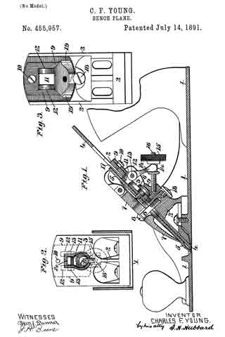
Figure 1 is a central longitudinal section of a plane constructed in accordance with my invention; Fig. 2, a plan view of the upper surface of the frog, the bit and cap-plate being removed, and Fig. 3, a rear view showing the frog and the swinging block, the adjusting-lever and its screw being removed.
The body and sole of the plane 1 are of any usual or ordinary construction, and 2 is a fixed frog, whose upper end is slotted, as shown at 3, Fig. 2, and against whose face the under side of the bit 4 is adapted to rest.
5 is a cap-plate of ordinary construction superposed upon the bit and secured thereto by a screw 6, as is common and usual, and 7 is a clamping-wedge which binds the bit against the frog by engagement with the screw 8. All of the foregoing is old and well known in the art of plane-making.
9 is a block, whose sectional shape is shown at Fig. 1 and whose outline appears at Fig. 3. Said block is pivotally secured to the frog by a screw or rivet 10, which passes through the upper end of said block and enters the frog, as is clearly shown at Fig. 1. Near its center said block has an opening 11, which when in assembled position registers with the opening 3 in the frog, and upon either side of said opening are lugs or cheeks 12. Between these cheeks is extended a pin 13, upon which a lever 14 is fulcrumed. The rear end of this lever is yoked, and the arms of the yoke engage an annular groove in a thumb-nut 15, which latter runs upon a screw 16, set in and projecting rearwardly from the thick lower portion of the block 9. By means of this lever-and-screw arrangement the longitudinal movement of the bit is effected, the nose of the lever 14 engaging either with a slot in the cap-iron, or, as shown in Fig. 1, in a slot cut in a small rectangular piece of metal 17, laid in the longitudinal slot of the bit and held in position by means of the screw 6.
18 is a screw let into the rear ot the frog in such manner that its head slightly overlaps the outer end of the block 9, so as to afford some support to said block, but not to interfere with the sidewise movement of the latter about its pivot.
In the operation of my invention the longitudinal movement of the bit may be freely accomplished through the nut 15, operating the lever 14 about its fulcrum, after the manner of the well-known Bailey plane, heretofore referred to. When it is desired to laterally adjust the bit, the block 9 may be swung sidewise upon its pivot beneath the frog, whereupon the engagementof the nose of the lever with the bed or cap plate will move the latter, operating thereon after the manner of a lever of the second order. As the lever and screw 14 16 are secured to the block and move with it, their operation is in no way affected by the movement of the block.
In this invention I am able to dispense with the levers, which have heretofore been formed independently and in some way connected to the bit, while at the same time I secure a very simple adjusting device which is economical to manufacture and from its position beneath the frog is neither liable to be injured nor its adjustment changed accidentally — as, for instance, by a fall of the plane. The rear edges of the block 19, as shown at Fig. 3, project sufficiently to admit of the ready operation of the block by the thumb or finger applied thereto.
I claim —
1. In a bench-plane, the combination, with the frog and the bit secured thereon, of a block piveted beneath the frog and adapted to have a swinging movement relative thereto, an adjusting-lever fulcrumed in said block and having operative engagement with the bit, and adjusting devices carried by said block, whereby through the lever the longitudinal movement of the bit is effected, substantially as described.
2. The combination, with the bit and the frog, of the adjusting-lever 14 and means for operating it for the longitudinal movement of the bit, and a block fulcrumed beneath the frog and adapted to move sidewise upon said frog, whereby a lateral movement is imparted to the adjusting-lever, substantially as described.
3. In a bench-plane, the combination, with the bit and frog, of the block 9, pivoted to the frog, as at 10, the lever 14, having operative engagement with the bit, and the screw device 15 16, whereby said lever is moved about its fulcrum, said block and lever adapted to be move laterally for the side adjustment of the bit about the pivot 10, substantially as described.
In testimony whereof I affix my signature in presence of two witnesses.
CHARLES F. YOUNG.
Witnesses:
ROBERT L. GILBERT,
ANDREW J. EWEN.