
| PLEASE NOTE: The images presented on this page are of low resolution and, as a result, will not print out very well. If you wish to have higher resolution files then you may purchase them for only $2.95 per patent by using the "Buy Now" button below. All purchases are via PayPal. These files have all been cleaned up and digitally enhanced and are therefore suitable for printing, publication or framing. Each zip package contains all the images below (some packages may contain more), and purchased files can be downloaded immediately. |

UNITED STATES PATENT OFFICE.
_________________
MICHAEL J. DUNN AND WILLIAM H. MONTGOMERY, OF COLUMBUS,
OHIO, ASSIGNORS TO THE OHIO TOOL COMPANY, OF SAME PLACE.
BENCH-PLANE.
_________________
SPECIFICATION forming part of Letters Patent No. 461,166, dated October 13, 1891.
Application filed April 15, 1891. Serial No. 389,038. (No model.)
_________________
To all whom it may concern:
Be it known that we, MICHAEL J. DUNN and WILLIAM H. MONTGOMERY, citizens of the United States, residing at Columbus, in the county of Franklin and State of Ohio, have invented certain new and useful Improvements in Bench-Planes; and we do hereby declare the following to be a full, clear, and exact description of the invention, such as will enable others skilled in the art to which it appertains to make and use the same.
Our invention relates to mechanical appliances for effecting the up-and-down or longitudinal and the lateral or sidewise adjustments of a bench-plane bit; and it consists, first, in a longitudinally-adjusting mechanism comprising a pivoted lever-link and a screw-threaded link, the former being pivoted to the base or frog-plate of the plane and connected with the cap-iron of the bit, and the latter also connected to a bracket of said frog-plate and provided with a thumb-nut, as will be hereinafter described, whereby the adjustment back and forward on an inclined plane in a longitudinal direction can be perfectly and readily effected, and, while this is the case, the parts for making such adjustment are readily accessible.
It consists, second, in a novel combination of the bit, cap-plate, slotted frog-plate, and a lever having its lower end pivoted in the slotted upper end of the frog-plate and pivotally connected at its lower end to the upper end of the bit. By this construction the lateral adjustment of the bit for the purpose of bringing its cutting-edge parallel with the face of the plane, and thereby securing an even cut, is cfected, and as the lever is pivoted at nearly the extreme upper ends of the bit and frog-plate we are enabled to use fully two inches of the cutting-bit before substituting a new one therefor, and, while this is so, the lever is in convenient location for being manipulated by the user of the plane.
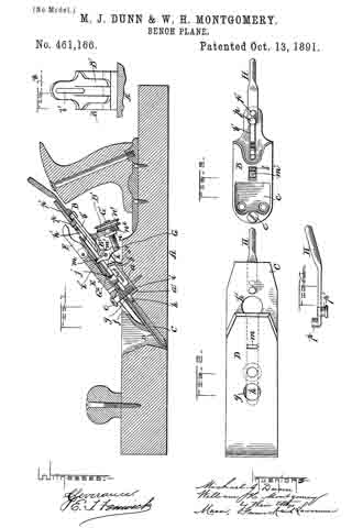
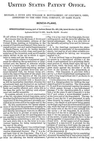
In the drawings, Figure 1 is a vertical longitudinal section of a bench-plane with our invention illustrated thereon. Fig. 1x is a detail back view of the frog-plate. Fig. 2 is a top view of the bit and its cap-plate, and the lever for effecting the lateral adjustment. Fig. 3 is a top view of the frog-plate, the connecting-screw, and the lever for effecting the lateral adjustment. Fig. 4 is a side view of the laterally-adjusting lever and its fulcrum-pivot.
A in the drawings represents the plane-stock, which is preferably of the construction shown, but may be of any other suitable construction adapted for having our invention applied to it.
B is an inclined base or frog-plate secured by screws in a shouldered mortise a, of the stock A and sustained by a projecting thickened portion b2, which bears upon the top of said stock, while the front end of the frog-plate abuts against the shoulder a’ at the front of the mortise of the plane-stock, as shown. This frog-plate is provided with a cavity c, a short longitudinal rectangular slot b, and a long longitudinal slot b’, as shown in the drawings.
C is the plane-iron; D, the cap-plate thereof, and E a clamping-plate for holding the cap-plate D and bit C in position. The three plates C, D, and E are connected together by a screw e, which passes through a key-hole-shaped passage f in the clamping-plate E, a round hole g in the plate D, and a long slot h in the bit C and enters a screw-threaded socket i at the lower end of the frog-plate B. The cap-plate D and the bit C are connected to each other directly by means of a headed nicked screw j, the shank of said screw being passed up through cap D and its end screwed into said cap, while the head of the screw binds against the under side of the bit C and extends into the cavity c of the frog-plate B, as shown. The slot h, of the bit is enlarged into a round hole h’ for the purpose of allowing the head of the screw j to pass through the bit C in the fitting together or separation of the cap-plate D and bit C. At the upper end of the clamping-plate E a cam-lever F is pivoted for the purpose of causing a bind upon the cap and keeping its front edge parallel with the edge of the bit C or at right angles with the sides of the plane-stock A.
G is a jointed adjusting device consisting of a screw-threaded link G’ and a lever-link G2, pivoted in the walls of the slot b of the frog-plate, as indicated at k’. The upper arm m’ of the part G2 of the jointed adjusting device is extended in width or laterally and enters an oblong transverse slot m, in the cap-plate D, the said oblong slot being of slightly greater area th an the end of the said arm, so as to permit freedom of movement of the bit C and cap D in a lateral direction, and also allow the said arm slight movement in a direction longitudinally of the plates, and thus prevent binding and interference during the manipulation of the parts in making the necessary lateral and longitudinal adjustments of the bit C. The lower arm kof the said portion G2 is pivoted to the slightly-inclined screw-threaded link G’, said screw-threaded link passing between the prongs of the bifurcated bracket B’ of the frog-plate B and being condfied therein, so as to act with a frictional bind against a too great descent after an adjustment is made, by means of a collar n and a milled button n’ of a nut n2, said nut ntting and receiving the screw-threaded portion of the said link G’, and its collar n bearing on or occupying a position in close proximity to the front side of the bracket, while the button bears against or occupies a position close to the rear side thereof, and the frictional bearing action taking place when the gravity of the link G’ is unrestrained by the hand of the operator. The link G’ and its nut n2 are free to slide up and down upon the bifurcated bracket when the said frictional binding action is relaxed and the shortening and lengthening of the lever-link-adjusting device is being effected. The relaxation of the binding action may, when necessary, be accomplished by slightly lifting the link G’ to a position at a right angle to the prongs of the bracket, this adjustment overcoming the binding action which takes place when the said link by its gravity moves slightly out of a right-angular position with the prongs of the bracket. By turning the nut n2 in one direction the said adjusting device G is brought to a straighter condition, and the arm m’ is forced forward and caused to move the bit C and cap-plate D on an inclined plane downward and forward, and thereby effect the necessary or desired longitudinal adjustment, which adjustment can be made with the greatest nicety and with great convenience, as the links G’ and G2 are both supported by extensions or projections of the frog-plate, as represented.
H is a hand-lever with its handle bent upward slightly. The lower portion of this lever, between its extreme lower end and its rear upwardly-bent end, is parallel with the under side of the bit C and upper side of the frog-plate B and occupies a position between said plates. The lower end of the lever is turned upward, so as to form a pivotal toe p, and this toe passes up through a hole or slot in the bit C, said hole or slot being not far from the upper end of said bit-plate, as shown. Just in rear of this toe a pivot-pin p’ is inserted and fastened to the lever, said pin working loosely in the longitudinal slot b’ of the frog-plate B, being held in said slot by means of a head formed on it, (the pivot,) as shown. By means of the lever H the bit C can be adjusted laterally, it being simply necessary to move the handle end of the lever slightly to the right or left, as occasion may require, in order to cause the toe go to force the upper end of the bit sufficiently far sidewise to bring the lower edge of said bit parallel with the face of the plane-stock. The slot b’ in the frog B allows the pivot p’ to change its altitude accordingly as may be necessary when the bit C is adjusted up and down.
By our laterally-adjusting means described simplicity is secured and reduction of cost effected, and about two inches of the cutting-bit can be utilized before it is thrown aside, which is important.
A further advantage results from attaching the lever for producing the lateral adjustment very near the upper end of the cutting-bit and at a greater distance from the point where the bit is clamped and held in place, as by this arrangement we secure more leverage and the movement of the bit is more readily effected. This is due to the fact that the pivot-pin of lever H can occupy a position at any point along the entire distance of the slot in the frog-plate — a result not practicable unless the parts are constructed and arranged as we show. It is by this construction that we are enabled to use the bit entirely up to the beginning of the slot. In our construction we use but one hole in the bit.
We are aware of Patent No. 378,498; but with such patented plane our invention could not be employed, as said plane uses only a single bit, while our invention can only be used with a double or capped bit, and, besides this, a longer slot must be provided than is shown in Patent No. 378,494 to permit the bit to be used entirely up to the beginning of the slot, and should a longer slot be adopted in said patent the hole therein shown would have to be done away with, and this would interfere with the using of the bit entirely up to the beginning of the slot.
What we claim as our invention is —
1. The jointed adjusting device G, comprising the lever-link G2 and the screw-threaded link G’, pivoted by its forward end to the link G2 and having nut n2 and button n’, in combination with the frog-plate B, having bracket B ‘, the bit C, and cap-plate D, the whole constructed and arranged substantially as described.
2. In a double or capped bit, in combination, a bit C, cap D, clamp E, frog-plate B, and lever H, provided with the toe p, extending above its upper surface at its forward end, and the pivot-pin p’ nearly at its forward end and extending downward from its lower surface, the said pivot-pin and toe of the lever being connected, respectively, with the frog-plate and the bit near their rear ends, and the said frog-plate being slotted, as at b’, forward of said points of attachment of the lever, substantially as described.
In testimony whereof we affix our signatures in presence of two witnesses.
MICHAEL J. DUNN.
WILLIAM H. MONTGOMERY.
Witnesses:
HERBERT E. BRADLEY,
WILLIAM E. JONES.