| PLEASE NOTE: The images presented on this page are of low resolution and, as a result, will not print out very well. If you wish to have higher resolution files then you may purchase them for only $2.95 per patent by using the "Buy Now" button below. All purchases are via PayPal. These files have all been cleaned up and digitally enhanced and are therefore suitable for printing, publication or framing. Each zip package contains all the images below (some packages may contain more), and purchased files can be downloaded immediately. |
UNITED STATES PATENT OFFICE.
_________________
GEORGE H. MELENDY, OF SAN FRANCISCO, CALIFORNIA,
ASSIGNOR OF ONE-HALF TO BENNETT BROTHERS, OF SAME PLACE.
PLANE ATTACHMENT.
_________________
SPECIFICATION forming part of Letters Patent No. 464,701, dated December 8, 1891.
Application filed January 14, 1891. Serial No. 377,761. (No model.)
_________________
To all whom it may concern:
Be it known that I, GEORGE H. MELENDY, a citizen of the United States, residing in the city and county of San Francisco, State of California, have invented an Improvement in Plane Attachments; and I hereby declare the following to be a full, clear, and exact description of the same.
My invention relates to an attachment for planes such as are in use by carpenters and others; and it consists, essentially, of means for adjusting and compensating the throat to the wear which takes place upon the bottom face of the plane by constant use, and in certain details of construction.
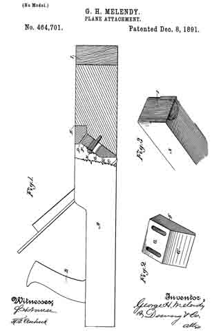
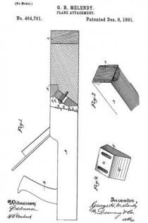
Referring to the accompanying drawings for a more complete explanation of my invention, Figure 1 is a longitudinal vertical section taken through the front of the plane showing the adjustment thereof. Fig. 2 is a view showing the throat-adjusting block removed. Fig. 3 is a perspective view of the front end of my plane.
A is the body of the plane having the handle B and the open throat C within which the plane-iron is fixed in any usual or suitable manner. When these plane~bodies are made of wood, they are subjected to considerable wear by reason of the friction of the lower face with the surface over which they are moved and which the plane-iron is intended to cut and dress, and as this wear takes place the throat for the escape of the shavings loses its proper proportion, thus necessitating some adjustment if the plane is to have any further use. In my invention I have shown the throat having an inclined chamber D made in the forward portion of it by inserting a piece E, a portion of the under surface of which is inclined and projects into the throat and forms the top wall of the inclined chamber, this chamber inclining into the forward portion of the body A. This piece E, which forms the chamber D, is designed to protect the adjustable block F and moving parts from dust or shavings, and it is important for the reason that without it they would become choked and clogged. Within this chamber below the block E is fitted a block F, the front portion of which rests upon the front portion of the incline in the chamber D, and the rear portion is made with two faces G and G’, meeting each other at an angle, as shown, the face G’ being approximately vertical when the plane is in its ordinary position. Through the upper portion of this block slots are made and screws H serve to fix it at any desired point.
When by considerable use the plane has been worn down, it will be manifest that by reason of the inclined rear face of the opening C upon which the plane-iron is supported the throat will become enlarged and will not be in proper shape for the best work. When this occurs, the screws or fastening of the movable throat-piece are loosened, and this piece is allowed to move downward, sliding upon the inclined surface of the front of the chamber, and this forces the surface G’ of the movable block nearer to the edge of the plane-iron. The block is moved downward until the throat is made of the proper size, when it is again secured in place. The lower end of the block which would be projected beyond the surface of the plane by this movement is cut off so that it is again flush with the surface of the plane. By this device the throat of the plane may be adjusted and retained at the proper size until the plane is entirely worn out. In connection with this device I have shown the inserted block I, having a rounded or convex surface, fitted into a channel or groove of semicircular form in cross-section, which is formed vertically in the front end of the plane. This block is secured in the channel with the grain of the wood extending vertically, so that the end grain is exposed at the bottom and flush with the surface of the plane. The object of this is to equalize the wear upon the plane, as it is well known that the front end of the plane which is first pushed over the rough surfaces of the work to be planed is worn and rounded off more rapidly than the other portions which are situated behind the plane-iron, and by reason of this hard inserted piece and the fact that the wear comes upon the end of the grain the wear will be equalized and the plane kept in proper condition much longer.
Having thus described my invention, what I claim as new, and desire to secure by Letters Patent, is —
1. In a plane having a plane-iron and a throat, a piece E, let into the throat so as to form an inclined chamber, an adjustable block in said chamber below the piece E, and screws passing through and adjustably securing the block, substantially as herein described.
2. In a plane, the body thereof having its front end formed with a vertical groove semi-circular in cross-section, and a piece having a convex rear surface fitting the groove so that its lower end is flush with the bottom of the plane, said inserted piece having its grain at right angles with the grain of the body, whereby it presents an end grain surface at the bottom to equalize the wear upon the plane, substantially as herein described.
In witness whereof I have hereunto set my hand.
GEORGE H. MELENDY
Witnesses:
A. B. MERRILL,
J. W. RICHARDS.


