

| PLEASE NOTE: The images presented on this page are of low resolution and, as a result, will not print out very well. If you wish to have higher resolution files then you may purchase them for only $2.95 per patent by using the "Buy Now" button below. All purchases are via PayPal. These files have all been cleaned up and digitally enhanced and are therefore suitable for printing, publication or framing. Each zip package contains all the images below (some packages may contain more), and purchased files can be downloaded immediately. |
UNITED STATES PATENT OFFICE.
_________________
EDMUND A. SCHADE, OF NEW BRITAIN, CONNECTICUT, ASSIGNOR TO
THE STANLEY RULE AND LEVEL COMPANY, OF SAME PLACE.
PLANE-IRON.
_________________
SPECIFICATION forming part of Letters Patent No. 473,087, dated April 19, 1892.
Application filed January 8, 1891. Serial No. 377,120. (No model.)
_________________
To all whom it may concern:
Beit known that I, EDMUND A. SCHADE, a citizen of the United States, residing at New Britain, in the county of Hartford and State of Connecticut, have invented certain new and useful Improvements in Plane-Irons, of which the following is a specification.
My invention relates to improvements in plane-irons; and the objects of my improvement are to facilitate the manufacture of the plane-iron, to improve its quality when made, and to make the plane-iron capable of being worn down farther than the old style of iron used in connection with certain planes.
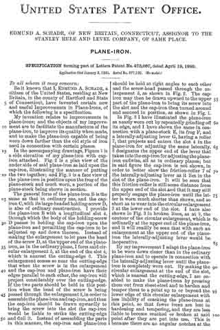
In the accompanying drawings, Figure 1 is a side elevation of my plane-iron with cap-iron attached. Fig. 2 is a plan view of the under side of said plane-iron as laid upon the cap-iron, illustrating the manner of putting the two together; and Fig. 3 is a face view of the plane-iron in position upon the frog of the plane-stock and much worn, a portion of the plane-stock being shown in section.
The general form of the plane-iron B is the same as that in ordinary use, and the cap-iron C, with its large-headed holding-screw D, is also of ordinary construction. I provide the plane-iron B with a longitudinal slot 4, through which the body of the holding-screw D passes in holding the cap-iron upon the plane-iron and permitting the cap-iron to be adjusted up and down thereon. Instead of making the enlargement to let pass the head of the screw D, at the upper end of the plane-iron, as in the ordinary plane, I form said circular enlargement 5, at the end of the slot 4, which is nearest the cutting-edge 6. This enlargement comes so near the cutting-edge that when the screw is in the enlargement and the cap-iron and plane-iron have their edges parallel to each other, the cap-iron will project considerably over the cutting-edge. If the two parts should be held in this position when the head of the screw is being passed through the enlargement 5, in order to assemble the plane-iron and cap-iron, and then the cap-iron should be drawn upwardly to bring the screw into the slot the cap-iron would be liable to strike the cutting-edge and dull it. Instead of assembling the parts in this manner, the cap-iron and plane-iron should be held at right angles to each other and the screw-head passed through the enlargement 5, as shown in Fig. 2. The cap-iron may then be drawn upward to the upper part of the plane-iron to bring its screw into the slot and the cap-iron then turned around and secured in position, as shown in Fig. 1.
In Fig. 3 I have illustrated the plane-iron as nearly worn out by repeatedly grinding off its edge, and I have shown the same in connection with a plane-stock E, its frog F, and a laterally-adjusting lever G, having a roller 7, that projects and enters the slot 4; in the plane-iron for adjusting the same laterally. 8 designates the upper end of the lever that takes into the cap-iron for adjusting the plane-iron endwise, all as in ordinary planes; but in said figure the cap-iron is not shown, in order to better show the friction-roller 7 of the laterally-adjusting lever as it lies in the slot of the plane-iron. It will be seen that this friction-roller is still some distance from the upper end of the slot and that it may still properly engage the plane-iron until the latter is worn much shorter than shown, and so short as to wear into the circular enlargement 5 at the lower end of the slot. I have also shown in Fig. 3 in broken lines, as at 9, the contour of the circular enlargement, which is ordinarily at the upper end of the plane-iron, and it will readily be seen that with such an enlargement at the upper end of the plane-iron the laterally-adjusting lever would be inoperative.
By my improvement I adapt the plane-iron to be worn down closer than in the ordinary plane-iron and to operate in connection with the laterally-adjusting lever until the plane-iron is completely worn cut. By making the circular enlargement at the end of the slot, which is nearest the cutting-edge, I am enabled to make the plane-irons by pressing them out from sheet-steel and to harden and temper them to a point up to or beyond the lower edge of this circular enlargement with less liability of cracking the plane-irons at this point, so that fewer irons are lost in hardening and tempering, and they are less liable to become cracked or broken at said point after they are put into use. This is because there are no angular notches at the lower end of the slot from which a crack will start, and because the slot opens into the circular enlargement, so that it is less liable to strain in the expansion and contraction of the metal during the hardening and tempering process. Care is generally taken in hardening the ordinary plane-bit not to harden it quite up to the slot ; but by my improvement such care is not necessary.
I claim as my invention —
In a plane, the combination of a plane-iron having a longitudinal slot 4 with the circular enlargement at its lower end, said slot extending up near to the upper end of the bit without any enlargement at said upper end, and a laterally-adjustilig lever having a projecting part fitted to work in the upper end of said slot, substantially as described, and for the purpose specified.
EDMUND A. SCHADE.
Witnesses:
H. S. WALTER,
F. N. STANLEY.