
| PLEASE NOTE: The images presented on this page are of low resolution and, as a result, will not print out very well. If you wish to have higher resolution files then you may purchase them for only $2.95 per patent by using the "Buy Now" button below. All purchases are via PayPal. These files have all been cleaned up and digitally enhanced and are therefore suitable for printing, publication or framing. Each zip package contains all the images below (some packages may contain more), and purchased files can be downloaded immediately. |
UNITED STATES PATENT OFFICE.
_________________
GRANVILLE W. WRIGHT, OF NEW HAVEN, CONNECTICUT,
ASSIGNOR TO THE SARGENT & COMPANY, OF SAME PLACE.
BENCH-PLANE.
_________________
SPECIFICATION forming part of Letters Patent No. 493,903, dated March 21, 1893.
Application filed October 19, 1891. Serial No. 409,156. (No model.)
_________________
To all whom it may concern:
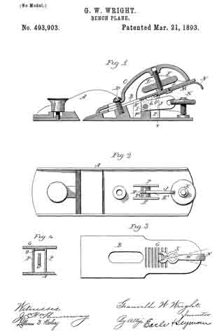
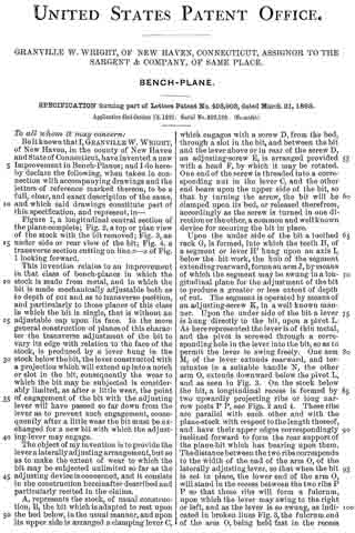
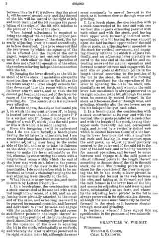
Be it known that I, GRANVILLE W. WRIGHT, of New Haven, in the county of New Haven and State of Connecticut, have invented a new Improvement in Bench-Planes; and I do hereby declare the following, when taken in connection with accompanying drawings and the letters of reference marked thereon, to be a full, clear, and exact description of the same, and which said drawings constitute part of this specification, and represent, in —
Figure 1, a longitudinal central section of the plane complete; Fig. 2, a top or plan view of the stock with the bit removed; Fig. 3, an under side or rear view of the bit; Fig. 4, a transverse section cutting on line x–x of Fig. 1 looking forward.
This invention relates to an improvement in that class of bench-planes in which the stock is made from metal, and in which the bit is made mechanically adjustable both as to depth of cut and as to transverse position, and particularly to those planes of this class in which the bit is single, that is without an adjustable cap upon its face. In the more general construction of planes of this character the transverse adjustment of the bit to vary its edge with relation to the face of the stock, is produced by a lever hung in the stock below the bit, the lever constructed with a projection which will extend up into a notch or slot in the bit, consequently the wear to which the bit may be subjected is considerably limited, as after a little wear, the point of engagement of the bit with the adjusting lever will have passed so far down from the lever as to prevent such engagement, consequently after a little wear the bit must be exchanged for a new bit with which the adjusting-lever may engage.
The object of my invention is to provide the lever a laterally adjusting arrangement, but so as to make the extent of wear to which the bit may be subjected unlimited so far as the adjusting device is concerned, and it consists in the construction hereinafter described and particularly recited in the claims.
A, represents the stock, of usual construction, B, the bit which is adapted to rest upon the bed below, in the usual manner, and upon its upper side is arranged a clamping lever C, which engages with a screw D, from the bed, through a slot in the bit, and between the bit and the lever above or in rear of the screw D, an adjusting-screw E, is arranged provided with a head F, by which it may be rotated. One end of the screw is threaded into a corresponding nut in the lever C, and the other end bears upon the upper side of the bit, so that by turning the screw, the bit will be clamped upon its bed, or released therefrom, accordingly as the screw is turned in one direction or the other, a common and well known device for securing the bit in place.
Upon the under side of the bit a toothed rack G, is formed, into which the teeth H, of a segment or lever H’ hung upon an axis I, below the bit work, the hub of the segment extending rearward, forms an arm J, by means of which the segment may be swung in a longitudinal plane for the adjustment of the bit to produce a greater or less extent of depth of cut. The segment is operated by means of an adjusting-screw K, in a well known manner. Upon the under side of the bit a lever is hung directly to the bit, upon a pivot L. As here represented the lever is of thin metal, and the pivot is screwed through a corresponding hole in the lever into the bit, so as to permit the lever to swing freely. One arm M, of the lever extends rearward, and terminates in a suitable handle N, the other arm O, extends downward below the pivot L, and as seen in Fig. 3. On the stock below the bit, a longitudinal recess is formed by two upwardly projecting ribs or long narrow posts P P, see Figs. 2 and 4. These ribs are parallel with each other and with the plane-stock with respect to the length thereof, and have their upper edges correspondingly inclined forward to form the rear support of the plane-bit which has bearing upon them. The distance between the two ribs corresponds to the width of the end of the arm O, of the laterally adjusting lever, so that when the bit is set in place, the lower end of the arm O, will stand in the recess between the two ribs P P so that these ribs will form a fulcrum, upon which the lever may swing to the right or left, and as the lever is so swung, as indicated in broken lines Fig. 3, the fulcrum end of the arm O, being held fast in the recess between the ribs P P, it follows that the pivot L, will be moved accordingly, and that the end of the bit will be turned to the right or left, and such turning of the bit changes the parallelism of the edge of the bit with relation to the plane of the face of the stock.
When lateral adjustment is required to bring the edge of the bit into the proper parallelism with the plane of the stock, the laterally adjusting lever is turned accordingly, as before described. It is to be observed that the two levers by which the squaring of the bit is effected and the depth of the cut is gaged, respectively, act entirely independently of each other so that the operation of one does not affect the operation of the other, the two levers having independent connection with the bit.
By hanging the lever directly to the bit instead of to the stock, it maintains always the same position with relation to the bit; as the bit wears away the lever simply extends farther downward into the recess within which its lower arm O, works, and so that the bit cannot get beyond the control of the lever because of the wearing away of the bit, as by grinding, &c. The construction is simple and very effective.
As herein shown, the axis or horizontal pin I, on which the segment or lever H’, is hung, is located between the said ribs or posts P P in a vertical slot P’, formed midway of the length of a web P2, which joins the said posts or ribs with which it is made integral.
From the foregoing it will be understood that I do not claim broadly a bench-plane having the bit laterally adjustable, but I am aware that planes have been constructed with a lateral adjusting lever hung to the under side of the bit, and so as to take its fulcrum on the stock, but in such case it has been necessary to make the lever adjustable on the bit, whereas by constructing the stock with a longitudinal recess within which the end of the lever may work as a fulcrum, the permanent hanging of the lever to the bit is made practicable. I do not therefore wish to be understood as broadly claiming hanging the lateral adjusting lever directly to the bit.
What I do claim as my invention, and desire to secure by Letters Patent, is —
1. In a bench-plane, the combination with a stock constructed at its rear end with a central longitudinal recess, of a bit, and an adjusting-lever pivotally attached to the outer end of the same, and extending rearward to be grasped for manual operation, and forward and downward to enter between and engage with the parallel side walls of the said recess at different points in the length thereof according to the position of the bit in the plane-stock, the said walls forming points of purchase for the operation of the lever in squaring the bit in the stock, substantially as set forth, and whereby the lever is always preserved in its right relation to the bit, although the same must constantly be moved forward in the stock as it becomes shorter through wear and grinding.
2. In a bench plane, the combination with a stock constructed at its rear end with two vertical ribs or posts extending parallel with each other and with the stock, and having their upper ends forwardly inclined correspondingly; of a bit having its rear support upon the said inclined upper ends of the said ribs or posts, an adjusting-lever mounted in the stock for vertical movement, and engaging directly with the bit which it adjusts vertically, and an adjusting lever pivotally secured to the rear end of the said bit, and extending rearward for manual operation and forward to enter between and engage with the said ribs or posts at different points in the length thereof according to the position of the bit in the stock, the said ribs forming points of purchase for the operation of the lever in squaring the bit in the stock, substantially as set forth, and whereby the said lever last mentioned is always preserved in its right relation to the bit, although the same must be constantly moved forward in the stock as it becomes shorter through wear, and grinding, whereby also the two levers act on the bit independently of each other.
3. In a bench-plane the combination with a stock constructed at its rear end with two vertical ribs or posts parallel with each other and with the length of the stock, having their upper ends forwardly inclined correspondingly, and joined by a vertically slotted web which is located between them; of a bit having its lower face provided with a longitudinal rack and having its rear support upon the said posts; an adjusting lever pivotally secured to the outer end of the said bit to the rear of the said rack, and extending rearward for manual operation, and forward to enter between and engage with the said posts or ribs at different points in the length thereof according to the position of the bit in the said stock, the said ribs forming points of purchase for the operation of the lever in squaring the bit in the stock; a lever pivoted in the vertical slot formed in the web between the ribs, and taking at its forward end into the rack formed in the lower face of the bit; and means for adjusting the said lever up and down, substantially as set forth, and whereby the adjusting lever pivoted to the bit is always preserved in its right relation thereto, although the same must constantly be moved forward in the stock as it becomes shorter through wear and grinding.
In testimony whereof I have signed this specification in the presence of two subscribing witnesses.
GRANVILLE W. WRIGHT.
Witnesses:
WILLIAM S. COOKE,
CHAS. L. BALDWIN.