
| PLEASE NOTE: The images presented on this page are of low resolution and, as a result, will not print out very well. If you wish to have higher resolution files then you may purchase them for only $2.95 per patent by using the "Buy Now" button below. All purchases are via PayPal. These files have all been cleaned up and digitally enhanced and are therefore suitable for printing, publication or framing. Each zip package contains all the images below (some packages may contain more), and purchased files can be downloaded immediately. |

UNITED STATES PATENT OFFICE.
_________________
LOUIS HARDT, OF YUBA CITY, CALIFORNIA.
PLANE.
_________________
SPECIFICATION forming part of Letters Patent No. 502,906, dated August 8, 1893.
Application filed November 3, 1892. Serial No. 450,873. (No model.)
_________________
To all whom it may concern:
Be it known that I, LOUIS HARDT, a citizen of the United States, residing at Yuba City, Sutter county, State of California, have invented an Improvement in Planes; and I hereby declare the following to be a full, clear, and exact description of the same.
My invention relates to planes and it consists, broadly, in a stock the sole of which in advance of the main body portion and the bit iron is vertically and longitudinally adjustable with respect to the main body portion and bit iron, the adjustment in one direction causing the adjustment in the other direction whereby the depth of the cut and capacity of the throat are simultaneously increased.
The main object of my invention is to provide for an adjustable exposure of the cutting edge of the bit-iron without changing the position of the iron.
Another object is, by the peculiar adjustable front piece, to not only regulate the exposure of the cutting edge of the bit-iron, but also to vary the capacity of the throat.
The accomplishment of these objects results in providing a plane easily set to the different kinds of work, said plane having a perfect bearing surface or guide behind the knife, whereby it cuts true and smooth.
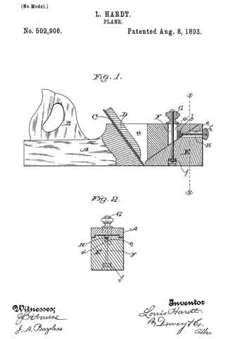
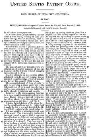
Referring to the accompanying drawings for a more complete explanation of my invention, — Figure 1 is a longitudinal, vertical section of my plane. Fig. 2 is a vertical transverse seetion on the line x–x of Fig. 1.
A is the flat-soled stock of the plane having the usual handle or toat B. In the stock is made the bed a in which is seated the bit-iron C held to place by the usual wedge D.
E is my movable or adjustable front piece of the stock. This is secured to the front of the stock in such a manner that it can move to and be fixed at diiferent heights, thereby exposing to a greater or less extent the cutting edge of the iron C. This front piece E forms the base or sole of the front portion of the stock, and it is obvious than when its sole is in line with the sole of the stock there is a perfectly smooth under surface throughout the length of the stock, and the cutting edge of the iron may come down to the plane of this surface, in which case it will not cut at all; but by moving the front piece E to a higher plane the cutting edge of the iron will be exposed, and by starting the plane at the end of the board it will cut a shaving equal in thickness to the exposure of said cutting edge, due to the elevation of the front piece E; or by starting the plane in the middle of the board and pressing down upon its forward edge, the cutting edge of the iron may catch a thin shaving and so start the necessary abutment or ridge behind which the iron may work forwardly, to plane the surface of the board. It is obvious that this movement of the piece E to different heights may be accomplished vertically, if desired. But I prefer, mainly for two reasons, namely, the accurate adjustment of the piece, and the varying of the capacity of the throat, to effect the imovement of the adjustable piece E upon an inclined plane, so that it moves both vertically and forwardly. To this end it will be seen that the top edge of the front piece E is inclined and fits under a corresponding incline on the undercut front of the stock in suitable guides therein, as shown in Fig. 2, so that its upward and forward movement is accurate. To hold this front piece in place and set it where adjusted, I have the following connections:
F is a vertical bolt passing down through an elongated slot a’ in the front portion of the stock and entering the piece E, its lower end engaging a nut f countersunk in said piece. The upper end of this bolt is provided with the head, furnishing a hand-hold G. By loosening this bolt the front piece E may be moved forwardly on its inclined plane, the bolt F moving in the slot a’; and it may be again tightened to hold the base E in the position desired.
In order to firmly secure the piece E, which on account of its inclined character, would be difficult with the bolt F alone, I have the horizontal stay bolt H which passes through an enlarged opening e in the movable front piece E, and enters the front of the stock A where it engages a countersunk nut h in said portion of the stock. This bolt has a head h’ whereby it may be easily operated. When bolt H is loosened the piece E may be moved. It will now be seen that by moving the front piece E forwardly and upwardly, its rear end will not only expose the cutting edge of the bit-iron C, but will also enlarge the throat. In a plane of this construction, there is no necessity for changing the position of the iron at all; but in case it be desired to reach hollow places the iron can be set out in the usual manner. For the planing of ordinary surfaces, however, the iron remains stationary and its set is effected by the adjustment of the front piece E. This plane has, therefore, a full and complete smooth bearing on the base or sole of its stock behind the iron, at all times, instead of as is usual, the formation of a hollow place behind a projecting iron, which has a tendency to produce a rocking of the stock.
In my plane a start can be made without resulting in a notch or imperfect place, and the set of the iron may be rapidly and accurately had by holding the plane at the end of the board and setting the front piece up to expose the required portion of the iron.
Having thus described my invention, what I claim as new, and desire to secure by Letters Patent, is —
1. In a plane, a stock the sole of which in advance of the main-body-portion and the bit-iron is vertically and longitudinally adjustable with respect to the main body-portion and bit-iron the adjustment in one direction causing the adjustment in the other direction, whereby the depth of the cut and capacity of the throat are simultaneously increased, substantially as herein described.
2. In a plane, a flat-soled stock having its forward end undercut on an upward incline in combination with a movable front piece forming the sole of the stock having a downward inclined upper surface in advance of the bit-iron, said piece having a downward inclined upper surface fitted under the inclined front of the stock, whereby it may move forwardly and upwardly to increase the exposure of the cutting edge of the iron and the capacity of the throat, substantially as herein described.
3. In a plane, a flat-soled stock having its forward end undercut on an upward incline, in combination with a movable front piece forming the sole of the stock in advance of the bit-iron, said piece having a downward inclined upper surface fitted under the inclined front of the stock whereby it may move forwardly and upwardly to increase the exposure of the cutting edge of the iron and the capacity of the throat, and suitable bolts connecting said front piece to the front of the stock, substantially as herein described.
4. In a plane, the combination of the flat-soled stock with its upward inclined undercut front, the fiat-soled movable front piece E of the stock having a downward inclined upper surface fitted to the inclined undercut front, and the securing bolt F fitted to said piece and movable in the front of the stock whereby the depth of the cut and the capacity of the throat are simultaneously increased, substantially as herein described.
5. In a plane, the combination of a flat sole stock with its upward inclined undercut front, the fiat sole movable front piece E of the stock having a downward inclined upper surface fitted to the undercut front the securing bolt F fitted to said piece and movable in the front of the stock, and the horizontal stay bolt F fitted to the front of the stock and piece E, whereby the depth of the cut and the capacity of the throat may be simultaneously increased, substantially as set forth.
In witness whereof I have hereunto set my hand.
LOUIS HARDT.
Witnesses:
H. A. SCHULTZE,
WM. F. BOOTH.