
| PLEASE NOTE: The images presented on this page are of low resolution and, as a result, will not print out very well. If you wish to have higher resolution files then you may purchase them for only $2.95 per patent by using the "Buy Now" button below. All purchases are via PayPal. These files have all been cleaned up and digitally enhanced and are therefore suitable for printing, publication or framing. Each zip package contains all the images below (some packages may contain more), and purchased files can be downloaded immediately. |

UNITED STATES PATENT OFFICE.
_________________
JOHN McKNIGHT, OF FREDERICTON, CANADA.
PLANE-GUIDE.
_________________
SPECIFICATION forming part of Letters Patent No. 507,378, dated October 24, 1893.
Application filed September 24, 1892. Serial No. 446,794. (No model.)
_________________
To all whom it may concern:
Be it known that I, JOHN McKNIGHT, of Fredericton, in the Province of New Brunswick and Dominion of Canada, have invented a new and Improved Plane-Guide, of which the following is a full, clear, and exact description.
My invention relates to improvements in plane attachments, and the object of my invention is to produce a cheap and simple guide which may be attached to any kind of a plane, which is adapted to guide the plane so as to enable the edge of a board to be planed perfectly true and square, and which also may be adjusted so as to guide the plane in such a manner as to plane the edge of the board on any desired bevel.
To these ends my invention consists in a plane guide, the construction of which will be hereinafter described.
Reference is to be had to the accompanying drawings forming a part of this specification, in which similar figures of reference indicate corresponding parts in both the views.
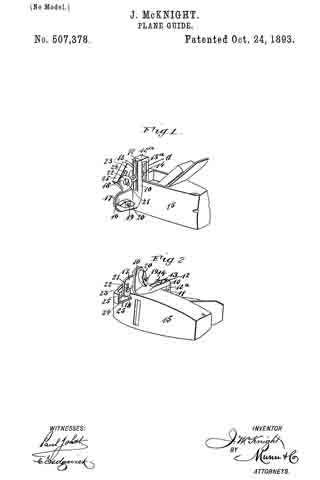
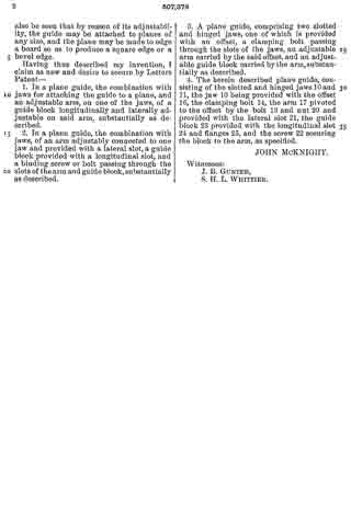
Figure 1 is a perspective view of the guide embodying my invention, showing it attached to a plane and with the guide block swung upward to permit the plane to be used in the ordinary way for surface planing; and Fig. 2 is a perspective view of the plane guide and plane showing the bottom of the plane and with the guide block in position for use.
The same guide is provided with two jaws or clamping pieces 10 and 11 which are adapted to be placed parallel with each other and fastened to the top portion of the plane to permit of the lateral adjustment of the jaws so as to enable them to straddle one side of the plane, as described below; they have what is substantially a hinge connection at the top, the jaw 11 having an onset 12a with a tongue 12 thereon which enters the upper portion of the jaw 10. The jaws 10 and 11 are provided with central vertical slots 13 and 13a through which extends a clamping bolt 14 having a suitable nut on one end, and by tightening the nut the jaws may be held together and clamped firmly to the plane 15. When the jaws are to be applied to the plane, the jaw 11 is placed inside the plane, that is, in the top recess of the plane, and the jaw 10 on the outside, as shown in Fig. 1. The jaw 10 has a laterally extending offset 16 at the bottom, on which is hinged an outwardly swinging arm 17, which arm has an outward bend at its free end, as shown at 18. The hinge connection between the arm 17 and offset 16, is formed by the bolt 19, which bolt is provided with a thumb nut 20 and by tightening the nut the arm 17 may be held in any desired position in relation to the offset 16.
The bent end 18 of the arm 17 is slotted laterally, as shown at 21, so as to permit the adjustment of the fastening screw 22 which is held in the arm, and this screw serves to bind the guide block 23 to the arm. This guide block is also slotted longitudinally, as shown at 24, and consequently the block and arm may be brought to any necessary position in relation to each other, the adjustment being necessary to enable the attachment to be applied to any kind of a plane.
The guide block 23 has at the end and on one side, a smooth flat bearing flange 25, the flange at the side of the block being adapted to fit against the side or edge of a board, and one of the end flanges being adapted to strike against the edge of the plane bottom, as shown in Fig. 2. When the guide block 23 is swung downward and fastened with its upper end against the plane bottom, the block will be held at right angles to the bottom of the plane, and if a board is to be edged, the guide block is permitted to run upon the flat face of the board and the plane knife is brought upon the edge so that a perfectly true and square edge may be produced even by a novice.
If the edge is to be planed on a bevel, the arm 17 and block 23 are adjusted so as to extend at an obtuse angle to the plane bottom, and when brought to the desired angle the thumb nut 20 is tightened so as to hold the arm securely in place, and by permitting the guide block to run upon the surface of the board, the edge may be planed on any desired bevel.
From the foregoing description it will be seen that this device is very cheap and simple, and the parts of it may be cast. It will also be seen that by reason of its adjustability, the guide may be attached to planes of any size, and the plane may be made to edge a board so as to produce a square edge or a bevel edge.
Having thus described my invention, I claim as new and desire to secure by Letters Patent —
1. In a plane guide, the combination with jaws for attaching the guide to a plane, and an adjustable arm, on one of the jaws, of a guide block longitudinally and laterally adjustable on said arrn, substantially as described.
2. In a plane guide, the combination with jaws, of an arm adjustably connected to one jaw and provided with a lateral slot, a guide block provided with a longitudinal slot, and a binding screw or bolt passing through the slots of the arm and guide block, substantially as described.
3. A plane guide, comprising two slotted and hinged jaws, one of which is provided with an offset, a clamping bolt passing through the slots of the jaws, an adjustable arm carried by the said offset, and an adjustable guide block carried by the arm, substantially as described.
4. The herein described plane guide, consisting of the slotted and hinged jawsc10 and 11, the jaw 10 being provided with the offset 16, the clamping bolt 14, the arm 17 pivoted to the offset by the bolt 19 and nut 20 and provided with the lateral slot 21, the guide block 23 provided with the longitudinal slot 24 and flanges 25, and the screw 22 securing the block to the arm, as specified.
JOHN McKNIGHT.
Witnesses:
J. B. GUNTER,
S. H. L. WHITTIER.