
| PLEASE NOTE: The images presented on this page are of low resolution and, as a result, will not print out very well. If you wish to have higher resolution files then you may purchase them for only $2.95 per patent by using the "Buy Now" button below. All purchases are via PayPal. These files have all been cleaned up and digitally enhanced and are therefore suitable for printing, publication or framing. Each zip package contains all the images below (some packages may contain more), and purchased files can be downloaded immediately. |
UNITED STATES PATENT OFFICE.
_________________
JUSTUS A. TRAUT AND CHRISTIAN BODMER, OF NEW BRITAIN,
CONNECTICUT; SAID BODMER ASSIGNOR TO SAID TRAUT.
PLANE.
_________________
SPECIFICATION forming part of Letters Patent No. 515,063, dated February 20, 1894.
Application filed August 9, 1893. Serial No. 482,771. (No model.)
_________________
To all whom it may concern:
Be it known that we, JUSTUS A. TRAUT and CHRISTIAN BODMER, citizens of the United States, residing at New Britain, in the county of Hartford and State of Connecticut, have invented certain new and useful Improvements in Planes, of which the following is a specification.
This invention relates to adjustable-mouth planes, the object being to furnish means for adjusting the mouth-slide and for holding the same in place.
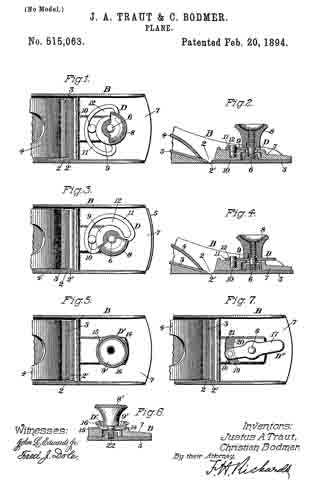
In the drawings accompanying and forming a part of this specification, Figure 1 is a plan view of a portion of a plane furnished with our present improvements. Fig. 2 is a sectional side view of the plane. Figs. 3 and 4 are views similar to Figs. 1 and 2, respectively, for illustrating the mode of operation of the improvement. Fig. 5 is a view-similar to Fig. 1, showing a modification of the improvement. Fig. 6 is a sectional side view of a portion of the same. Fig. 7 is a view similar to Fig. 1, showing another modiication.
Similar characters designate like parts in all the figures.
Referring to Figs. 1, 2, 3 and 4, the letter B designates the forward portion of an ordinary iron smoothing-plane of the class which are usually provided with a mouth-slide, also sometimes designated as an “adjustable front,” for regulating the width of the mouth 2, of the plane. The usual plane-iron or cutter is shown in place at 3, held under the forward end of the ordinary clamp, 4, in a well known manner.
The mouth-slide designated by 5, is shown provided with a stud, 6, preferably rigidly fixed therein as indicated in Figs. 2 and 4. Said stud 6 extends upward through the forward end, 7, of the plane-frame, and is provided on its threaded upper end with a clamping nut, 8, whereby to hold the mouth-slide in place.
According to our present improvements, the plane is furnished with a mouth-slide actuator, designated in a general way by D, and whose principal portion constitutes an adjustable block or thrust member, designated by 9, intermediate to some part of the mouth-slide and a suitable fixed stop-abutment, as, for instance, the pin 10, on the plane-frame. In the preferred form thereof shown in Figs. 1 to 4 inclusive, said actuator consists, essentially, of an eccentric disk 9; this is shown provided with a loop or outer bar, 11, bearing against the opposite side of the aforesaid abutment-pin 10, as clearly shown in said figures. By turning the actuator D toward the right-hand or left-hand, as for instance from the position shown in Figs. 1 and 2 to that shown in Figs. 3 and 4, the mouth-slide will be moved, in the present instance toward the right-hand for widening the open space, 2′ , between said slide and the cutter 3, as will be seen by comparison of said figures of the drawings. The actuator D, being set on the plane-frame underneath the clamp-nut 8, is thereby rigidly held in place when said nut is screwed down for holding the mouth-slide.
The actuator D is shown pivotally supported on the stud 6 of the month-slide 5, so that in connection with the actuator slot 12, and the abutment-pin 10, said actuator holds the mouth-slide positively against movement in either direction; said abutment-pin fitting closely but freely within said slot, and the forward and rearward sides of said pin constituting oppositely-disposed stop-abutments.
In Figs. 5 and 6 we have shown a modification of the invention, in which the actuator, here designated by D’, consists of an eccentric disk 9’, which fits on the clamp-screw 8’, and works between the forward and rearward abutrnents 14 and 15, of the plane-frame (see Fig. 6) so as to control the position of the mouth-slide in substantially the same manner as described in connection with Figs. 1 to 4 inclusive. Said disk 9′ is shown furnished with a knurled rim 16, whereby the operator may conveniently turn the actuator for adjusting the mouth-slide.
In Fig. 7 there is shown a further modification of the improvement, in which the actuator D” consists of a flat lever 17, fitted over the stud 6, (this being the same as the one shown in Figs. 1 to 4 inclusive) and having a pin or stud, 18, fitting in an eccentric groove, 19, between the forward and rearward abutments 20 and 21, formed on the plane-frame and corresponding to those shown in Figs. 5 and 6 and also (in reverse order) to the forward and rearward sides of the abutment-pin 10 shown in Figs.1, 2, 3 and 4. In Fig. 7, the clamp-nut is omitted for the purpose of more clearly illustrating the other features; but it is or may be the same as the one shown in Figs. 2 and 4. In Figs. 5 and 6, the clamp-screw 22 is shown formed integral with the head 8’, and in working engagement with the corresponding internal thread of the mouth-slide, as will be understood from Fig. 6.
Having thus described our invention, we claim —
1. In a plane, in combination, aplane frame having a stop-abutment upon the upper face thereof, a mouth-slide having a fixed stem, vertical thereto, an independently operable mouth-slide actuator supported upon the upper face of the plane-frame and engaging the stem and stop-abutment so as to rotate about said stem and against said abutment, and means for clamping said actuator against the plane-frame, substantially as described.
2. In a plane, in combination, the plane-frame having an abutment or stop upon the upper face thereof, a mouth-slide, a stern fixed at one end to the mouth-slide and having a clamp-nut adjustably secured to its opposite end, an independently operable eccentric loosely carried by the stem intermediate to the upper face of the frame and the clamp-nut and in engagement with the abutment, substantially as described and for the purpose set forth.
JUSTUS A. TRAUT.
CHRISTIAN BODMER.
Witnesses:
G. W. TRAUT,
H. C. HINE.