
| PLEASE NOTE: The images presented on this page are of low resolution and, as a result, will not print out very well. If you wish to have higher resolution files then you may purchase them for only $2.95 per patent by using the "Buy Now" button below. All purchases are via PayPal. These files have all been cleaned up and digitally enhanced and are therefore suitable for printing, publication or framing. Each zip package contains all the images below (some packages may contain more), and purchased files can be downloaded immediately. |
UNITED STATES PATENT OFFICE.
_________________
JUSTUS A. TRAUT, OF NEW BRITAIN, CONNECTICUT.
PLANE.
_________________
SPECIFICATION forming part of Letters Patent No. 516,413, dated March 13, 1894.
Application filed September 1, 1893. Serial No. 484,544. (No model.)
_________________
To all whom it may concern:
Be it known that I, JUSTUS A. TRAUT, a citizen of the United States, residing at New Britain, in the county of Hartford and State of Connecticut, have invented certain new and useful Improvements in Planes, of which the following is a specification.
This invention relates to that class of planes in which the plane-iron is adjustable for the purpose of bringing the same accurately into position for use, by means of adjusting-devices connected with the knife-holding apparatus.
The object of my present invention is to provide means, in a plane of the class specified, for adjusting the knife laterally thereof to bring the cutting-edge in parallelism with the face of the plane; and to make this adjustment by means of devices operating in connection with, but separately from (in point of time) the means for adjusting the plane-iron longitudinally thereof.
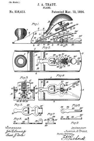
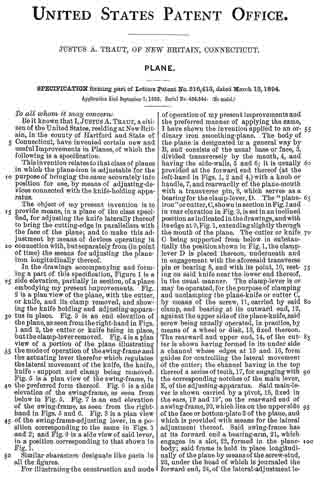
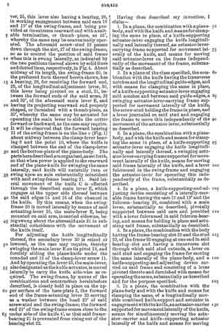
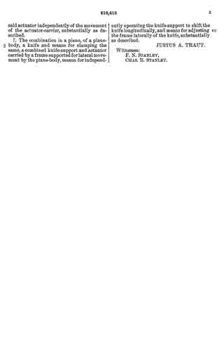
In the drawings accompanying and forming a part of this specification, Figure 1 is a side elevation, partially in section, of a plane embodying my present improvements. Fig. 2 is a plan view of the plane, with the cutter, or knife, and its clamp removed, and showing the knife holding and adjusting-apparatus in place. Fig. 3 is an end elevation of the plane, as seen from the right-hand in Figs. 1 and 2, the cutter or knife being in place, but the clamp-lever removed. Fig. 4 is a plan view of a portion of the plane illustrating the mode of operation of the swing-frame and the actuating lever therefor which regulates the lateral movement of the knife, the knife, knife-support and clamp being removed. Fig. 5 is a plan view of the swing-frame, in the preferred form thereof. Fig. 6 is a side elevation of the swing-frame, as seen from below in Fig. 5. Fig. 7 is an end elevation of the swing-frame, as seen from the right-hand in 5 and 6. Fig. 8 is a plan view of the swing-frame-adjusting lever, in a position corresponding to the same in Figs. 1 and 2; and Fig. 9 is a side view of said lever, in a position corresponding to that shown in Fig. 1.
Similar characters designate like parts in all the figures.
For illustrating the construction and mode of operation of my present improvements and the preferred manner of applying the same, I have shown the invention applied to an ordinary iron smoothing-plane. The body of the plane is designated in a general way by B, and consists of the usual base or face, 3, divided transversely by the mouth, 4, and having the side-walls, 5 and 6; it is usually provided at the forward end thereof (at the left-hand in Figs. 1, 2 and 4,) with a knob or handle, 7, and rearwardly of the plane-mouth with a transverse pin, 3, which serves as a bearing for the clamp-lever, D. The “plane-iron” or cutter, C, shown in section in Fig. 1 and in rear elevation in Fig. 3, is set in an inclined position as indicated in the drawings, and with its edge at 9, Fig. 1, extending slightly through the mouth of the plane. The cutter or knife C being supported from below in substantially the position shown in Fig. 1, the clamp-lever D is placed thereon, underneath and in engagement with the aforesaid transverse pin or bearing 8, and with its point, 10, resting on said knife near the lower end thereof, in the usual manner. The clamp-lever is or may be operated, for the purpose of clamping and unclarnping the plane-knife or cutter C, by means of the screw, 11, carried by said clamp, and bearing at its outward end, 12, against the upper side of the plane-knife, said screw being usually operated, in practice, by means of a wheel or disk, 13, fixed thereon.
The rearward and upper end, 14, of the cutter is shown having formed in its under side a channel whose edges at 15 and 16, form guides for controlling the lateral movement of the cutter, the channel having in the top thereof a series of teeth, 17, for engaging with the corresponding notches of the main lever, E, of the adjusting-apparatus. Said main-lever is shown carried by a pivot, 18, fixed in the ears, 19 and 19′, on the rearward end of a swing-frame, 20, which lies on the upper side of the face or bottom-plate 3 of the plane, and which is provided with means for the lateral adjustment thereof. Said swing-frame has at its forward end a bearing-arm, 21, which engages in a slot, 22, formed in the plane-body; said frame is held in place longitudinally of the plane by means of the screw-stud, 23, under the head of which is journaled the forward end, 24, of the lateral-adjustment lever, 25, this lever also having a bearing, 26, in working engagement between said ears 19 and 19′ of the swing-frame, and being provided at its extreme rearward end with a suitable termination, or thumb-piece, as 25′, whereby the same may be conveniently operated. The aforesaid screw-stud 23 passes down through the slot, 27 of the swing-frame, so as to control the position of said frame when this is swung laterally, as indicated by the two positions thereof shown by solid lines and dotted lines, respectively, in Fig.4. About midway of its length, the swing-frame 20, in the preferred form thereof herein shown, has a bearing, 28, for receiving the forward end, 29, of the longitudinal-adjustment lever, 30, this lever being pivoted on a stud, 31, between the forward ends of the said arms, 32 and 32′, of the aforesaid main lever E, and having its projecting rearward end properly shaped, or furnished with a thumb-piece, as 30′, whereby the same may be actuated for operating the main lever to slide the cutter forward or backward, as the case may require. It will be observed that the forward bearing 21 of the swing-frame is on the line e (Fig. 1) about midway between the clamp-lever bearing 8 and the point 10, where the knife is clamped between the end of the clamp-lever and the bottom-plate of the plane-body. The parts here described are organized, as set forth, so that when power is applied to the rearward end of the plane-knife for swinging the same laterally, said knife will naturally turn or swing upon an axis substantially coincident with said swing-frame bearing 21. Said lateral movement of the knife C is effected through the described main lever E, which engages at the upper side thereof between the said edges 15 and 16 of the channel in the knife. By this means, when the swing-frame 20 is moved laterally by means of said actuating-lever 25, the main-lever E, being mounted on said arm, is carried sidewise, being swung about the aforesaid axis 21 in substantial coincidence with the movement of the knife itself.
For adjusting the knife longitudinally thereof, the secondary lever 30 is raised or lowered, as the case may require, thereby swinging the main lever E on its pivot 18, and forcibly sliding the plane-knife under the rounded end 12 of the clamp-lever screw 11. And by operating the lever 25, the main-lever, also designated as the knife-actuator, is moved laterally to carry the knife side-wise as required. The swing-frame, by means of the combinations and construction hereinbefore described, is closely held in place on the upper surface of the base-plate 3, the forward end of the frame-actuating lever 25 serving as a washer between the head 23′ of said screw-stud and the swing-frame; the forward end 21′ of the swing-frame comes close to the under side of the knife C, so that said frame-bearing 21 is prevented from rising out of the bearing-slot 22.
Having thus described my invention, I claim —
1. In a plane, the combination with a plane-body, and with the knife and means for clamping the same in place, of a knife-supporting actuator-lever engaging the knife longitudinally and laterally thereof, an actuator-lever-carrying frame supported for movement laterally of the knife, and means for moving said actuator-lever on the frame independently of the movement of the frame, substantially as described.
2. In a plane of the class specified, the combination with the knife having the transverse notches and the longitudinal guide-edges, and with means for clamping the same in place, of a knife-supporting actuator-lever engaging said notches and between said guide-edges, a swinging actuator-lever-carrying frame supported for movement laterally of the knife, the screw-stud holding the frame in place, and a lever journaled on said stud and engaging the frame to move this independently of the movement of the actuator-lever, substantially as described.
3. In a plane, the combination with a plane-body, and with the knife and means for clamping the same in place, of a knife-supporting actuator-lever engaging the knife longitudinally and laterally thereof, a swinging actuator-lever-carrying frame supported for movement laterally of the knife, means for moving said frame laterally of the knife, and a lever fulcrumed. in the swing-frame and engaging the actuator-lever for operating this independently of the frame, substantially as described.
4. In a plane, a knife-supporting-and-adjusting device consisting of a laterally-movable frame having the ears 19 and 19′ and the fulcrum-bearing 28, combined with a main lever, substantially as described, pivotally supported between said ears and provided with a lever fulcrumed in said fulcrum-bearing, and means for holding in place and actuating said frame, substantially as described.
5. In a plane, the combination with the body having the frame-bearing slot 22 and the stud 23, of the frame 20 engaging at one end in said bearing-slot and having a transverse slot through which said stud extends, a lever on said stud and engaging the frame for moving the same laterally of the plane-body, and a knife-supporting-and-adjusting device carried on said frame and consisting of a lever pivoted thereto and furnished with means for operating the same, substantially as described and for the purpose specified.
6. In a plane, the combination with the plane-body and with the knife and means for clamping the same, of a longitudinally movable combined knife-support and actuator in engagement with the knife, an actuator-carrier supported for movement laterally of the knife, means for simultaneously moving the actuator-carrier and knife-supporting actuator laterally of the knife and means for moving said actuator independently of the movement of the actuator-carrier, substantially as described.
7. The combination in a plane, of a plane-body, a knife and means for clamping the same, a combined knife-support and actuator carried by a frame supported for lateral movement by the plane-body, means for independently operating the knife-support to shift the knife longitudinally, and means for adjusting the frame laterally of the knife, substantially as described.
JUSTUS A. TRAUT
Witnesses:
F. N. STANLEY,
CHAS. B. STANLEY.