
| PLEASE NOTE: The images presented on this page are of low resolution and, as a result, will not print out very well. If you wish to have higher resolution files then you may purchase them for only $2.95 per patent by using the "Buy Now" button below. All purchases are via PayPal. These files have all been cleaned up and digitally enhanced and are therefore suitable for printing, publication or framing. Each zip package contains all the images below (some packages may contain more), and purchased files can be downloaded immediately. |
UNITED STATES PATENT OFFICE.
_________________
JACOB W. TRIPP, OF SALT LAKE CITY, UTAH TERRITORY.
PLANE.
_________________
SPECIFICATION forming part of Letters Patent No. 516,780, dated March 20, 1894.
Application filed June 12, 1893. Serial No. 477,337. (No model.)
_________________
To all whom it may concern:
Be it known that I, Jason W. TRIPP, a citizen of the United States, residing at Salt Lake City, in the county of Salt Lake and Territory of Utah, have invented certain new and useful Improvements in Planes, of which the following is a description, reference being had to the accompanying drawings, and to the letters of reference marked thereon.
My invention relates to planes, and more particularly to means for adjusting the bit.
It consists in the various matters hereinafter described and claimed, and is illustrated in the accompanying drawings, in which —
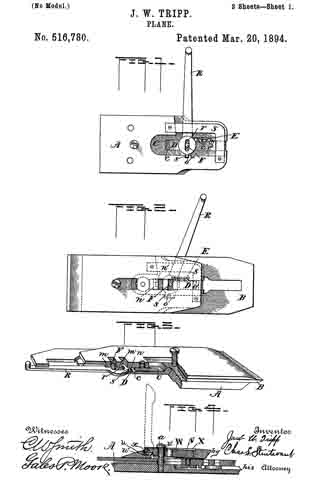
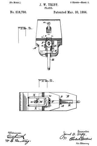
Figure 1 is a plan view of the bit plate illustrating more particularly the mechanism by which the bit is raised and lowered. Fig. 2 is a plan view with pressure cap removed showing lever mechanism in dotted lines. Fig. 3 is a perspective partly in section to show the means for adjusting the bit laterally. Fig. 4 is a detail of the pressure cap. Fig. 5 is a detail of the parts for adjusting the bit laterally; and Fig. 6 is a view of the top of the pressure cap.
In the drawings, A is a bit plate and B the bit. Hitherto it has been customary to provide a thumb screw or something similar thereto by which the bit is adjusted vertically, while the lateral adjustment has been effected by an additional member, in most cases a lever. I propose, however, to so construct the plane that one lever shall serve for both adjustments.
In order to provide a chamber for the necessary mechanism, I cut away a portion of the bit plate to form the part C and in the bottom of this I provide a groove c in which slides the block D, held in any position to which it may be brought by a suitable spring E. This spring may be of many constructions but I prefer to use that shown in the drawings, in which a spring plate is provided with projections e, which engage with teeth e’ on the side of the sliding block. A pin F projects from the sliding block and fits between the lugs m formed upon the bit cap so that when the block is moved it carries with it the bit, this being clamped to the bit cap in the usual manner. Another lug n provided with a recess n’ is formed upon the bit cap, while in the side of the bit plate, I provide one or more recesses o, these recesses being preferably dovetailed in order to more firmly hold the projection s for the purpose hereinafter set forth.
A lever R which projects above the rear portion of the bit when the plane is in position for use, is provided with a slot r fitting over the pin F, while upon its inner end is a projection s. A plate of metal S is fastened to the higher portion of the bit plate to prevent the lever from falling out of place when the bit is removed.
The operation of my device will be readily understood. Normally the projection s its in the recess n’ so that when the lever is moved to one side or the other, the pin F acting as a fulcrum, the edge of the bit will be correspondingly adjusted. To raise and lower the bit, the elongated slot r permits the lever to be drawn back until the projectionsis out of engagement with the recess n’, when the lever is turned to the right, the projection s is caught in one of the recesses o and as this projection then becomes a fulcrum, the sliding plate is moved by swinging the end of the lever. When the bit has been raised or lowered as desired, the lever is returned to its normal position.
While I prefer to employ the construction herein illustrated and described, it is manifest that many modifications may be made without in the least departing from the spirit of my invention.
It will be noticed that the lugs m, m and n, are so disposed that two slots for the reception of the pin F are provided instead of one, as found in planes of ordinary construction. The object of this is to adapt the bit for use with plane beds of different lengths.
Another feature of my invention is the pressure cap. At present, it is customary to provide caps with a hinged cam at their upper ends, these caps bearing upon the plane bit at two points only, viz., along the bottom of the pressure cap and at the point at which the cam touches the bit cap. The difficulty with this construction is that no pressure is exerted upon the main portion of the bit, and the result is that in planing hard wood, a slight spring is allowed that portion of the bit between the two bearing points of the pressure cap, thus permitting a slight vibration of the bit. In my device, however, I provide a plate u cut U-shaped as shown, and having its sides connected at the rear by a plate v of spring steel or other suitable material. To this plate v is attached a block W provided with an opening w for the plane bolt a projecting as usual from the bit plate, said block resting at its forward end upon the ledge u’ of the plate u. Hinged to the sides of the block is a yoke X having cams x adapted to bear upon the ledge u’. It will readily be seen that when the yoke of the pressure cap is raised, thus throwing the cams x up from the ledge u’, the cap may be slipped in position upon the plane, and upon the yoke being lowered, the plate u will be forced down upon the bit cap, its upper side resting against the head of the screw a as a fulcrum, bearing upon it with uniform force on the pressure cap’s entire under surface.
Having thus described my invention, what I claim as new, and desire to secure by Letters Patent, is —
1. A plane comprising a bit, a bit plate, a block sliding in said bit plate and connected to the bit, a lever connected to the sliding block, and means whereby said lever may be connected with either the bit or the bit plate; substantially as described.
2. A plane comprising a bit provided with a recess, a bit plate provided with a recess, a block sliding in said bit plate, and connected to the bit, and a lever-connected to the sliding block, said lever being adapted to engage either the bit recess or that formed in the bit plate; substantially as described.
3. A plane comprising a bit provided with a recess, a bit plate provided with a recess, a block sliding in said bit plate, a projection upon said block, a depression upon the bit adapted to receive the projection upon the block, a lever provided with a slot fitting over the projection upon the sliding block, and a projection upon said lever adapted to engage with either the bit recess or the recess formed in the bit plate; substantially as described.
4. A plane comprising a bit, a bit plate, ways in said bit plate, a block sliding in said ways and connected to the bit, a spring bearing against one edge of the block and the adjacent way, a lever connected to the sliding block, and means whereby said lever may be connected with either the bit or the bit plate; substantially as described.
5. A plane comprising a bit, a bit plate, ways in said bit plate, a recess formed in one of said ways, a spring plate in said recess, projections upon said spring plate, a block: sliding in said ways, teeth upon the side of the block adjacent to the spring in the way, a lever connected to the sliding block, and means whereby said lever maybe connected with either the bit or the bit plate; substantially as described.
6. A plane comprising a bit provided with a recess, a bit plate having a chamber C formed therein, a groove in said chamber, a block sliding in said groove, a projection upon said sliding block, a depression upon the bit and adapted to receive the projection upon the block, a recess in one wall of the chamber C, a lever provided with an elongated slot fitting upon the projection on the sliding block, a projection upon the lever adapted to engage either the bit recess or the recess formed in the bit plate, and a plate connecting the walls of the chamber; substantially as described.
7. A pressure cap for planes comprising a plate, an opening in said plate, a block hinged to said plate and provided with an opening for the insertion of the plane bolt, and means for raising the free end of the block against said plane bolt; substantially as described.
8. A pressure cap for planes comprising a U-shaped plate, a ledge connecting the lower portions of the sides of the plate, a spring plate connecting the upper ends of the sides of the plate, a block secured at one end to the spring plate and at the other resting upon the said ledge, an opening in said block for the passage of the plane bolt, a yoke hinged to the block at that end. which rests upon the ledge, and cams upon the yoke at its hinged end; substantially as described.
In testimony whereof I affix my signature in presence of two witnesses.
JACOB W. TRIPP.
Witnesses:
JOHN F. CORKER,
GERTRUDE E. CORKER.