
| PLEASE NOTE: The images presented on this page are of low resolution and, as a result, will not print out very well. If you wish to have higher resolution files then you may purchase them for only $2.95 per patent by using the "Buy Now" button below. All purchases are via PayPal. These files have all been cleaned up and digitally enhanced and are therefore suitable for printing, publication or framing. Each zip package contains all the images below (some packages may contain more), and purchased files can be downloaded immediately. |
UNITED STATES PATENT OFFICE.
_________________
WILLIAM E. CROMPTON, OF PARK CITY, UTAH TERRITORY.
CARPENTER’S PLANE.
_________________
SPECIFICATION forming part of Letters Patent No. 518,521, dated April 17, 1894.
Application filed July 14, 1893. Serial No. 480,526. (No model.)
_________________
To all whom it may concern:
Be it known that I, WILLIAM E. CROMPTON, a citizen of the United States, residing at Park City, in the county of Summit and Territory of Utah, have invented certain new and useful Improvements in Carpenters’ Planes; and I do hereby declare the following to beafull, clear, and exact description of the invention, such as will enable others skilled in the art to which it appertains to make and use the same.
My invention relates to improvements in planes, and especially to improvements in rabbet planes, and it consists of certain novel features hereinafter described and claimed.
The ordinary rabbet plane cuts a shaving somewhat wider than the plane, and this jams in the sides of the plane, rendering it necessary to stop to remove the same, and causing the inconvenience in working well known to persons skilled in the art. I have discovered that by splitting the shaving longitudinally, or rather by cutting a longitudinal slit in the wood before the shaving is pared oif by the bit, this inconvenience is almost entirely obviated.
My invention will be understood by reference tot he acccompanying drawings, in which the same parts are indicated by the same letters throughout the several views.
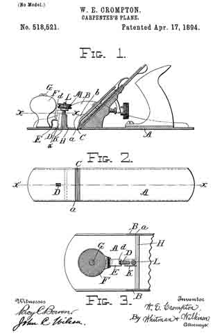
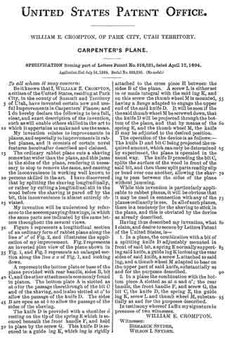
Figure 1 represents a longitudinal section of an ordinary form of rabbet plane along the line x’ x’ of Fig. 2, and illustrates the application of my improvement. Fig. 2 represents an inverted plan view of the plane shown in Fig. 1, and Fig. 3 represents an enlarged section along the line x x of Fig. 1, and looking down.
A represents the bottom plate or base of the plane provided with rear handle, sides B, bit C, and the other attachments commonly found in planes. The bottom plate A is slotted as at afor the passage therethrough of the bit C and of the shaving, and is also slotted at a’ to allow the passage of the knife D. The sides B are open as at b to allow the passage of the sides of the shaving.
The knife D is provided with a shoulder d resting on the tip of the spring E which is secured beneath the front handle F, and held in place by the screw G. This knife D is secured in a guide lug K, which lug is rigidly attached to the cross piece H between the sides B of the plane. A screw L is either set in or made integral with the said lug K, and on this screw the thumb wheel M is mounted, having a flange adapted to engage the upper end of the said knife D. It will be seen if the the said thumb wheel M be screwed down, that the knife D will be projected through the bottom of the plane, and that by means of the spring E, and the thumb wheel M, the knife D may be adjusted to the desired position.
The operation of the device is as follows: — The knife D and bit G being projected the required amount, which can only be determined by experiment, the plane is operated in the usual way. The knife D preceding the bit C, splits the surface of the wood in front of the said bit, and then these split parts readily slip or bend over one another, allowing the shaving to pass between the sides of the plane without jamming.
While this invention is particularly applicable to rabbet planes, it will be obvious that it may be used in connection with any of the planes ordinarily in use. In all of such planes, there is a tendency for the shaving to stick in the plane, and this is obviated by the device as already described.
Having thus described my invention, what I claim, and desire to secure by Letters Patent of the United States, is —
1. In a plane, the combination with a bit of a splitting knife D adjustably mounted in front of said bit, a spring E normally supporting said knife, a guide lug K inclosing the rear sides of said knife, a screw L attached to said lug, and a thumb wheel M adapted to bear on the upper part of said knife, substantially as and for the purposes described.
2. In a plane the combination with the bottom piece A slotted as at a and a’, the rear handle, the front handle F, and screw G, the bit C, the knife D, the spring E, the guide lug K, screw L and thumb wheel M, substantially as and for the purposes described.
In testimony whereof I affix my signature in presence of two witnesses.
WILLIAM E. CROMPTON.
Witnesses:
BISMARCK SNYDER,
WILSON I. SNYDER.