
| PLEASE NOTE: The images presented on this page are of low resolution and, as a result, will not print out very well. If you wish to have higher resolution files then you may purchase them for only $2.95 per patent by using the "Buy Now" button below. All purchases are via PayPal. These files have all been cleaned up and digitally enhanced and are therefore suitable for printing, publication or framing. Each zip package contains all the images below (some packages may contain more), and purchased files can be downloaded immediately. |
UNITED STATES PATENT OFFICE.
_________________
ROYAL W. McINTYRE AND GUSTAVUS A. H. SPRAGUE, OF REDLANDS, CALIFORNIA.
LUBRICATOR.
_________________
SPECIFICATION forming part of Letters Patent No. 518,823, dated April 24, 1894.
Application filed January 23, 1893. Serial No. 459,385. (No model.)
_________________
To all whom it may concern:
Be it known that we, ROYAL WARNER McINTYRE and GUSTAVUS ADOLPHUS HANKINSON SPRAGUE., of Redlands, in the county of San Bernardino and State of California, have invented certain new and useful Improvements in Oil-Cups; and we do hereby declare the following to be a full, clear, and exact description of the invention, such as will enable others skilled in the art to which it appertains to make and use the same.
Our invention is an improvement in oil cups or cans designed for greater simplicity and durability of construction and efficiency and certainty of operation.
A further object of our invention is to supply simple and useful means for lubricating the under surface of iron planes thereby dispensing with the old method of greasing the under surface of the plane with a piece of fat.
Other objects and advantages of the invention will appear in the following description in which we have set forth fully the details of construction and the essential features thereof and illustrated them in the accompanying drawings in which similar letters of reference designate corresponding parts.
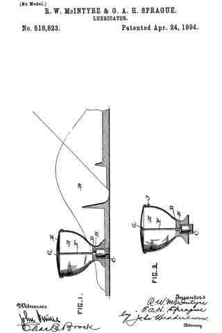
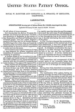
Figure 1 represents a part section and side view of an ordinary plane with our invention attached. Fig. 2 is a modification.
Reference being had to the above figures A represents the main body of the oil cup which is secured to the forward portion of the plane B by means of the hollow threaded lug C. The bottom of the cup A is provided with the conical hole D the smaller end of which is at the upper surface of the bottom. The upper portion of the cup A is furnished with a convex screw cap E which is made of light spring material and is screwed to the cup in the manner shown in Fig. 1. Extending upward through the conical hole D is the valve rod F one end of the stem of which is screwed to the projection G on the under surface of the cap E while its other end terminates in a conical enlargement H corresponding to the opening in the lower surface of the cup A. It will be readily seen that when the cap E is pressed downward the valve stem F and enlargement H are forced downward thus allowing the oil to flow through the hole in the bottom of the cup A thereby lubricating the under surface of the plane.
In Fig. 2 we have changed the construction slightly and instead of the conical hole D we have substituted a hole with parallel sides and constructed the enlargement H to correspond. In this latter construction the cup is adapted to be filled through the opening in the side of the cap near the top which is closed by a screw J. It will be readily seen that it is impossible for the oil to escape from the nozzle unless the base of the can is forced inward.
The construction and arrangement of the several parts of our invention being thus made known the operation and advantages of the same will it is thought be readily understood.
Having thus fully described our invention, what we claim, and desire to secure by Letters Patent, is —
The combination with a plane, having an opening through the bed of the front portion thereof, of an oil cup resting on said bed, and having a spring actuated valve therein which is operated from the upper end, and a screw plug, C, seated within the perforated base of the cup with an opening therethrough by means of which the said oil cup is secured to the bed plane, the upper portion of said plug being formed with an enlarged chamber, with which said valve communicates, and a lower reduced opening, and the lower end of said plug extending only partially through the side of the plane, substantially as described.
In testimony whereof we have signed this specification in the presence of two subscribing witnesses.
R. W. McINTYRE.
G. A. H. SPRAGUE.
Witnesses:
NAT A. BLAKE,
O. A. MOSTLING.