
| PLEASE NOTE: The images presented on this page are of low resolution and, as a result, will not print out very well. If you wish to have higher resolution files then you may purchase them for only $2.95 per patent by using the "Buy Now" button below. All purchases are via PayPal. These files have all been cleaned up and digitally enhanced and are therefore suitable for printing, publication or framing. Each zip package contains all the images below (some packages may contain more), and purchased files can be downloaded immediately. |
UNITED STATES PATENT OFFICE.
_________________
JUSTUS A. TRAUT, OF NEW BRITAIN, CONNECTICUT.
RABBET-PLANE.
_________________
SPECIFICATION forming part of Letters Patent No. 533,329, dated January 29, 1895.
Application filed October 8, 1894. Serial No. 525,202. (No model.)
_________________
To all whom it may concern:
Be it known that I, JUSTUS A. TRAUT, a citizen of the United States, residing at New Britain, in the county of Hartford and State of Connecticut, have invented certain new and useful Improvements in Rabbet-Planes, of which the following is a specification.
This invention relates to rabbet-planes, and it has for its principal object to furnish an improved plane of this general class, which may he readily converted from an ordinary rabbet-plane to a “bull-nose” plane without decreasing or adding to the number of parts of the tool.
Another object of the invention is to furnish an improved clamping-device for this kind of planes, by means of which the plane-iron or cutter may be securely and positively held substantially upon its longitudinal axis.
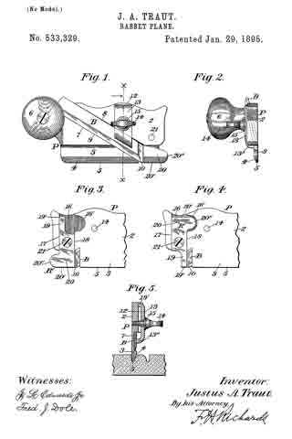
In the drawings accompanying and forming a part of this specification, Figure 1 is a side elevation of a rabbet-plane embodying my present invention. Fig. 2 is a front elevation of the same. Fig. 3 is a side elevation of a portion of the forward end or toe of the plane, looking toward the side opposite that shown in Fig. 1, and showing a reversible, auxiliary duplex runner in position to form an ordinary side-rabbet-plane. Fig. 4 is a view similar to Fig. 3, but showing the reversible member in position to form a “bull-nose” side-rabbet-plane. Fig. 5 is a transverse section taken in line x–x, Fig. 1, looking in the direction of the arrow and illustrating one use of the plane.
Similar characters designate like parts in all of the views.
In rabbet-planes as heretofore constructed it has been the practice to provide one form of plane for working in continuous open grooves, or cuts, and a separate, or “bull-nose,” plane for working in grooves or cuts closed at one or both ends thereof.
It is the main object of the present invention to combine the ordinary rabbet-plane and the “bull-nose” plane so that the two may be readily and quickly converted from one to the other, without decreasing or adding to the number of parts thereof, while at the same time maintaining the strength and solidity of the ordinary forms of plane of these types now in use. I attain this end by the provision of an auxiliary reversible member, or duplex runner removably secured to the forward end of the plane, in such a manner as to be fixedly held against movement laterally and longitudinally of the stock when in position thereon, and so that, when in either of its positions, one of the runners will have its sole in alignment with the sole of the stock, and will also have a vertical stop-face adjacent to the cutting edge of the plane-iron or cutter and adapted to close the chip-space or throat of the plane.
My invention also contemplates the provision of a clamp, adapted to be held positively in position substantially upon its longitudinal axis, so that the end thrust upon the cutter, when the plane is in use, will not loosen the clamp, but will be taken up by a fixed portion of the stock.
In the preferred embodiment of my invention, herein shown and described, P designates the stock of the plane, and is shown herein as comprising a body-portion 2, and a runner 3, of reduced cross-section, having the usual beveled face 4 sloping toward the outer side of said runner to form the usual narrow sole 5. This stock is shown herein as of substantially rectangular outline, and as provided at the upper rear end thereof with a handle 6, which may be of any desired construction. This handle is shown as formed separately from the stock and as secured thereto by a screw fastening but it is obvious that it might be integral with the stock. An oblique channel is shown, at 7, as extending from the upper, inner corner of the plane to the lower, outer corner thereof, and is adapted for maintaining the cutter or bit in position. The walls of this channel are shown as parallel with each other, and as intersecting the outer face of the plane in a line perpendicular with the sole thereof, so as to form an inner stop-wall for the outer side of the cutter-iron, and thereby maintain the cutting-edge of said iron perpendicular to the plane of the sole of the stock.
The plane-iron or bit is designated in a general way by B, and is shown as having parallel, longitudinal edges, and as adapted to lit snugly within the guides, 8 and 9, which form the upper and lower walls of the channel 7. This bit or cutter is also shown as beveled at its forward end to form a cutting edge 10, which, when the cutter is in position, will be substantially perpendicular to the sole of the stock, and is represented as beveled also adjacent to its lower, longitudinal edge, to conform with the outline of the beveled runner 3, and prevent interference with the work, which might result from the projection of a portion of the cutter beyond the inner, beveled edge of the runner.
The stock is shown herein as having formed upon its inner side a channel or guide-way 12, perpendicular to its sole but inclined to the sides of said stock at the same angle as is the channel 7, and adapted to position a clamping-device for locking the cutter against the walls of said channel 7, the two guide-ways or channels being shown as intersecting each other.
The clamping-device for securing the cutter is shown as comprising a locking-member or bridge-piece 13, having a body portion, non-contiguous to the stock, and two transverse terminal members or clamping faces, 13′ and 13”, the latter of which is disposed obliquely of the body-portion, so that when in position it will engage the inner face of the bit substantially upon the longitudinal axis thereof. This bridge-clamp is shown as provided with a central aperture or opening adapted for the reception of a clamping thumb-screw 14, the outer screw-threaded end of which engages a correspondingly-threaded aperture or tap, passing through the body portion of the plane, at a point substantially centrally-disposed relatively to the side-walls of the guide-way 12.
A washer 15 may be provided, if desired, between the head of the clamp-screw and the face of the bridge-piece.
It will be seen that, when the cutter is in position and the bridge-clamp is adjusted between the walls of the channel 12, if the body-portion of the clamp is forced or sprung inwardly toward the inner wall of the stock by the clamp-screw, all the pressure exerted will be transmitted to the two locking-faces 13′ and 13”, and that the cutter will be securely engaged and maintained in position, as the side edges of the clamp 13 engage against the walls of the guideway and fill the same so that there can be no movement of the clamp until the screw is released.
Pressure upon the cutter during the operation of the plane is transmitted to the clamp in such a way as to be received against the vertical stop-walls of the guide-way 12, and hence the clamp can not work loose.
At the forward end of the outer side of the stock, a channel or guide-way, shown at 16 as disposed substantially perpendicularly to the sole of the plane, is formed, and said channel is provided with a rearwardly-extending re-
cess or countersunk portion 16′, the transverse wall of which is described by a curve which is shown as approximately a semi-circle, but it will be understood that this recess or countersink might be of a different conformation, if desired. The forward end of the stock is shown herein as undercut to thepoint where the channel 7, or cutter-way, intersects the outer face of the plane to the sole of the runner thereof, but for only a portion of this distance.
An auxiliary reversible, member, designated in a general way by R’, and having reversible runners separately adapted to be brought into alignment with the main runner to form therewith a continuous sole, is shown herein as adapted to be seated within said channel or guide-way, and to be maintained against longitudinal movement, relatively to the stock, by the vertical stop walls, 17 and 18, thereof. This auxiliary runner is shown as of partially rectangular outline —
that is to say, it is formed with parallel front and rear walls, and with transverse parallel soles perpendicular to said front and rear walls. Said duplex runner is shown herein as having at each of its upper and lower ends a runner and a sole, designated, respectively, by 19, 19’, 20 and 20′. Each of said, runners is beveled to correspond with the beveled edge of the runner of the stock, one of said beveled faces being shown in Fig. 1. One end of this auxiliary runner is shown herein as of considerable length, and as having a toe-portion or nose, 20”, extending slightly beyond the forward end of the stock in the manner common to side-rabbet-planes as ordinarily constructed. The other end of said duplex runner is shown as having a very short runner formed by undercutting this end of the auxiliary member for a considerable distance, so that when said auxiliary member is secured to the stock in the position shown in Fig. 4, the construction willbe that of a “bull-nose” plane, the toe-portion or nose of which extends under the forward end of the stock and is but slightly in advance of the cutting edge of the bit. In order that said auxiliary runner may be properly positioned, without unnecessary adjustment thereof, I have shown the same as provided herein with an aperture or opening, extending through the same transversely thereof, at a point centrally located with respect to both the vertical, parallel outer walls and the horizontal, parallel outer walls thereof, and as secured to the stock, within the guide-way 16, by a locking device, which is shown herein as a screw 21, passing through the central opening in said stock and into a correspondingly-threaded opening therein, which latter opening is so placed as to be at the same perpendicular distance from the main sole (extended), as is the opening in the auxiliary, duplex runner from the soles 19′ and 20′. It will, be seen, therefore, that, when the auxiliary stock is secured in position by the screw 21, in either of its positions the sole of the corresponding runner will be in exact alignment with the sole of the runner upon the stock. The parallel, vertical walls of the duplex runner are so disposed as to engage snugly against the corresponding, forward and rearward stop-walls of the guide-way 16, so that longitudinal movement of the auxiliary runner, relatively to the stock, is positively prevented.
It will be understood that the laterally-extending recess 16′ is merely to form a seat for the nose 20″, and may be of any desired outline so long as it is of sufficient area to inclose the same; and also, that the outer faces of the stock and the duplex runner, when the parts are assembled form a continuous, plane surface, which presents no obstruction to the surface against which it may be held when the plane is in use, the head of the screw 21 being flush with or sunken below the outer face of the auxiliary runner, and the point of the clamping screw also being flush with the outer face of the stock.
By means of the reversible, auxiliary member just described it will be evident that, by simply removing the screw 21 and reversing the position of said auxiliary member, the plane may be quickly changed from an ordinary rabbet-plane to a “bull-nose” rabbet-plane and vice versa, without changing any of the parts thereof, so that the plane may be readily and quickly adapted for use for smoothing the sides of grooves or cuts which are continuous from end to end of the material being operated upon, or which extend but part-way along the material and are closed at their ends, which latter require a plane having a very short nose extending but slightly in advance of the cutter. It will also be noticed that the rearward, vertical wall of the auxiliary runner closes the throat of the plane and forms the forward wall of said throat in both of its positions.
A perfect convertible-plane is formed by the combination with the main stock of an auxiliary runner of the character described, whereby the plane may be adapted for use either as an ordinary rabbet-plane or as a “bull-nose” rabbet-plane, by the removal and re-setting of a single screw and the member secured thereby.
Having thus described my invention, I claim —
1. In a rabbet-plane, the combination with the stock and its runner, of an auxiliary member adapted to be secured to said stock and to close the throat of the plane and having oppositely-disposed runners separately adapted to be brought into alignment with the main runner upon the stock and form with said runner a continuous sole, substantially as described.
2. In a rabbet-plane, the combination with the stock and its runner, and with the cutter secured to said stock, of an auxiliary member adapted to be secured to the stock and to close the throat of the plane and formed with oppositely-disposed runners having respectively projecting and undercut portions forming auxiliary runners adapted to be separately brought into alignment with the main runner upon the stock and to form therewith a continuous sole, whereby said plane is adapted for use either as an ordinary rabbet-plane or as a “bull-nose” rabbet-plane, substantially as described.
3. In a rabbet-plane, the combination with the stock and its runner, and with the cutter secured to said stock, of a vertically-disposed channel or guide-way at the forward end of said stock, a reversible auxiliary member adapted to be seated in said guide-way and having oppositely-disposed long and short runners separately adapted to be brought adjacent to and to close the throat of the plane, and securing means in position and adapted for securing said auxiliary member in said guideway with the sole of either of its runners in alignment with the main sole of the stock, and thereby adapting the plane for use either as an ordinary rabbet-plane or as a “bull-nose” rabbet-plane, substantially as described.
4. In a rabbet-plane, the combination with a stock having a throat open at its forward side, and with a runner carried by said stock, of a reversible duplex auxiliary runner secured to the stock and adapted in either of its positions to close the throat of the plane and to form with the main runner a continuous runner and sole, and stops carried by said stock and adapted to prevent longitudinal movement of said auxiliary runner relatively to the stock, substantially as described.
5. In a rabbet-plane, the combination with a stock having an obliquely-disposed channel, a cutter mounted therein, and a vertically-disposed guide-way intersecting said channel, of a bridge clamp seated in said guide-way and held therein against movement longitudinally of the stock and having remotely-disposed locking-faces one of which is adapted to engage the rear wall of said guide-way and the other of which is adapted to engage the cutter substantially upon the axial line thereof, and a clamping-screw passed through said clamp and into the stock and adapted to bind said clamp to the cutter, substantially as described.
JUSTUS A. TRAUT.
Witnesses:
FRED. J. DOLE,
FREDERICK A. BOLAND.