
| PLEASE NOTE: The images presented on this page are of low resolution and, as a result, will not print out very well. If you wish to have higher resolution files then you may purchase them for only $2.95 per patent by using the "Buy Now" button below. All purchases are via PayPal. These files have all been cleaned up and digitally enhanced and are therefore suitable for printing, publication or framing. Each zip package contains all the images below (some packages may contain more), and purchased files can be downloaded immediately. |

UNITED STATES PATENT OFFICE.
_________________
JUSTUS A. TRAUT, OF NEW BRITAIN, CONNECTICUT.
PLANE.
_________________
SPECIFICATION forming part of Letters Patent No. 536,746, dated April 2, 1895.
Application filed January 12, 1895. Serial No. 584,626. (No model.)
_________________
To all whom it may concern:
Be it known that I, JUSTUS A. TRAUT, a citizen of the United States, residing at New Britain, in the county of Hartford and State of Connecticut, have invented certain new and useful Improvements in Planes, of which the following is a specification.
This invention relates to planes, and especially to that class of tools, commonly known as smooth-planes; and it has for its object to provide an improved plane, adapted for supporting the plane-knife adjacent to the cutting end thereof, and to do this by means which are adapted for adjusting the position of the plane-knife or iron, relatively to the forward wall of the plane-mouth.
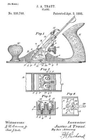
In the drawings, accompanying and forming part of this specification, Figure 1 is a vertical, longitudinal section of a smooth-plane embodying my present invention. Fig. 2 is a plan view of a portion of the plane, for illustrating certain features of construction of the same. Fig. 3 is a transverse section, taken in line a–a, Fig. 1, looking in the direction of the arrow, and Fig. 4 is a detail, sectional, plan view of an adjusting device for adjusting the position of the knife carrier, relatively to its seat in the plane.
Similar characters designate like parts in all the figures.
My present improvements comprise, in combination with a plane having a transverse mouth, a knife-carrier seat in the rear of, and inclined toward said mouth, a knife carrier supported by said seat, and having a knife-engaging face inclined toward the mouth of the plane at a relatively-greater inclination to the face or sole of the plane, than that of the knife-carrier-engaging face of the knife-carrier seat, the knife-carrier being adapted for movement along said face of its seat, means for securing the knife-carrier against movement relatively to the seat, and a knife adapted to be secured to said knife-engaging face of the carrier, so that, when the carrier is moved relatively to the forward wall of the plane-mouth, the knife itself will also be correspondingly actuated, and the area of the chip-space increased or decreased, in accordance with such movement.
My invention also comprises, in combination with the aforesaid knife-carrier and its support, means for adjusting the carrier upon, and relatively to the support, and holding the carrier in its adjusted position.
The plane-body, which is designated in a general way by B, is, or may be, in its principal features, of any ordinary or desired construction, adapted for co-operating with those elements in which my invention particularly resides, and this plane-body is shown herein, as provided with the usual handle H, at the rearward end thereof, and with the knob or actuating-handle H’, at the forward end of the same. The plane-body has formed in the face or sole thereof, the usual transverse mouth 2, the forward wall of which is designated by 2’; and, rearward of the plane-mouth, the plane-body is shown as having a knife-carrier seat or support inclined toward said mouth, and having its inclined face at a comparatively slight inclination, relatively to the face of the plane. This knife-carrier seat, which is designated herein by S, may be in the form of a solid member, extending transversely entirely across the body of the plane, or it may comprise a pair of similarly-inclined, longitudinal shoulders, extending but a short way from each of the sides of the plane, and inwardly toward the longitudinal center of the same. In the latter case, however, an intermediate, and preferably similarly-inclined member must also be provided, for a purpose which will hereinafter appear. The inclined face of this seat S, is shown herein as relatively adjacent, at its forward end, to the face or sole of the plane, and this inclined face is adapted to receive a knife carrier or bracket, designated in a general way by C, which carrier is organized to support the knife, and to be engaged and held by the seat S, to thereby prevent movement of the carrier relatively to such seat. This seat S, is much thicker at all points than the base 3, of the plane, or at least, is of a considerably greater thickness at a point a short distance in the rear of the rear wall 2” of the plane-mouth, which wall is herein shown, as formed by the forward edge of said seat. The relatively-greater thickness of this knife-carrier seat S, or of a portion of said seat, is necessary for the purpose of forming therein threaded holes, or bores 4–4, with which may engage holding means, preferably in the form of binding-screws 5–5, for securing the carrier C, to said seat.
It will be evident that, if the upper or carrier-engaging face of the seat S were in a plane parallel with the face, or sole 3′ of the frame, the forward end of the bracket would, as in the present practice, lie so far above the sole 3′, that the forward end and cutting-edge of the knife would be insufliciently supported. As the carrier-engaging face of the seat is forwardly and downwardly inclined, toward the plane-mouth, and as the forward end of the carrier-engaging face of this seat is relatively adjacent to the plane-sole or face 3’, the carrier or bracket C, will be supported with its forward end in close proximity to the extreme forward and under edge of said knife-carrier seat S, and also in close proximity to the cutting-edge of the knife or plane-iron itself, which plane-iron is designated herein by K. By this organization of the parts, it will be evident that the carrier or bracket C, will be adjustable in an oblique direction toward, and from the face or sole 3′ of the plane, and also toward and from the forward wall 2′ of the plane-mouth, so that, when the knife is drawn backward on the knife-engaging face of the carrier, and the carrier is moved downwardly on the inclined face of the seat S, to close the plane-mouth, in performing the most accurate work with the plane, the knife, or plane-iron, is supported close to its cutting-edge, as is necessary for such work. By this peculiar construction and organization of the knife-supporting members of the plane, the most perfect adjustment of the plane-knife for depth of cut, and in longitudinal direction for regulating the area of the chip-space, is obtainable, and, moreover, the most perfect possible support for the plane-knife, that is, a rigid support, most nearly adjacent to the cutting-edge of such knife, also results.
As before stated, the inclination of the carrier-supporting surface of the member S, is such that the body of said support is of considerable thickness, so that an ample thickness of metal is obtained at the line a–a, in which to form the holes 4–4, for the binding-screws 5–5; and this support is also sufficiently thick to permit the employment of screws of relatively-large bore and length, so that the carrier may be rigidly held thereby to the body of the plane.
The means for holding the plane-knife, or plane-iron K, upon the carrier, or bracket C, and for adjusting the knife, may be of any ordinary or suitable construction.
In the present case, the plane-knife is shown as resting upon the inclined, upper face of the carrier, the usual cap 8, being affixed to said knife.
A lever 9, is shown as pivoted at 9’, to the carrier C, and has its upper end in engagement with the cap, for actuating the same toward, and from the plane-mouth, and thereby moving the plane-iron in the same direction. This lever has the usual, forked tail-piece, engaged by a peripheral groove in an adjusting-nut 10, which works longitudinally upon the screw or threaded-post 12, fixed to the carrier.
The plane-knife and cap are shown as clamped in position, against the knife-supporting face of the carrier, by means of the usual clamp-lever 13, working against the fulcrum-screw 14, set into the carrier C, said clamp-lever being controlled in its clamping or releasing position, by means of the actuating cam-lever 15, pivoted at the rear end of said clamp-lever, and having its cam-face in operative engagement with the upper face of the cap 8, all of these holding devices being of ordinary construction, and well known in the art. The carrier C, is normally maintained in engagement with the upper face of the seat S, by means of the binding-screws 5–5, hereinbefore referred to, and these screws are preferably passed through a portion of the carrier, which has its upper face in a plane parallel with the lower or seat-engaging face of the carrier, in order that the carrier maybe moved relatively to seat, without affecting the positioning of these binding-screws. In order to obtain this result, the carrier is shown as having recesses, such as 17–17, countersunk therein, and formed with the end walls thereof parallel with the under side of the carrier.
The binding-screws 5–5, which preferably have washers 5′–5’, between the heads thereof and the end walls of said recesses, are also shown as passed through openings in the relatively-thin walls 13, formed by these recesses 17–17, and which openings are somewhat elongated longitudinally of the plane-body.
It will be evident that when the carrier is moved along the seat S, relatively thereto, these slots 19–19, will permit the screws to maintain their same relation to the seat S, and hold the carrier securely upon said seat. These binding-screws may be loosened, if desired, to permit this adjustment of the carrier, but this adjustment is preferably effected by means of a suitable adjusting device, such as is shown in Figs. 1 and 4 of the drawings. This adjusting device, which is designated in a general way by A, and which is shown as a cam-faced lever 20, is pivoted at its forward end, for movement in a plane coinciding with the plane of the bearing-face of the knife-carrier C, by means of a pin 21, engaging in a socket or recess 21’, in the seat S. Said lever is also shown as formed with a cam-groove 22, disposed substantially transversely of the lever and engaging the depending-lug or stud 23, on the under side of the carrier C. It will be evident that, upon the actuation of this lever 20, the carrier, engaging the cam-groove thereof, by its stud 23, will be actuated longitudinally of the plane, and the area of the chip-space correspondingly increased or decreased, by the advance of the forward edge of said carrier toward the front wall 2′ of the plane-mouth, or its recession therefrom.
After this adjustment of the carrier, the binding-screws 5–5, if loosened prior to the adjustment, will be re-tightened, and the plane-iron set in place and made ready for use. When the adjusting device for this carrier is of a sufficiently powerful character, this preliminary loosening of the binding-screws will be found unnecessary, the binding-screws having been previously so set as to hold the carrier firmly in place without entirely preventing movement of the same, the frictional engagement between said binding-screws and the carrier, and the carrier-engaging face of the seat S, being sufficient to maintain an adjustable, clamping connection between said carrier and its seat with the binding-screws.
Having thus described my invention, I claim —
1. In a plane, in combination, a plane-body having a substantially-transverse mouth, and having also a continuous-plane knife-carrier seat adjacent to, and rearward of, said mouth, and inclined vertically relatively to the plane-sole; a V-shaped knife-carrier having two independent and relatively-diverging continuous-plane bearing-faces, one of which is, throughout the length thereof, in engagement with the plane-knife, and the other of which is movably-supported substantially throughout the length thereof upon the inclined knife-carrier-seat of the plane-body; a plane-knife adjustably carried upon the upper face of said carrier, and means in connection with, and adapted for, adjusting said carrier longitudinally of, and at an inclination to the plane-sole, substantially as described, and for the purpose set forth.
2. In a plane, in combination, a plane-body having a substantially-transverse mouth, and having also a continuous-plane knife carrier-seat adjacent to and rearward of said mouth, and inclined vertically relatively to the plane-sole; a V-shaped knife-carrier adjusting-lever supported for movement in the plane of the carrier-seat and in operative engagement with, and adapted for, adjusting the knife-carrier longitudinally of said seat, and at an inclination to the plane-sole; and a knife adjustably carried upon the knife-carrier, substantially as described.
3. In a plane, the combination with a plane-body having a substantially transverse mouth, and having also an inclined knife-carrier seat adjacent to, and in the rear of said mouth and sloping toward the mouth; of a knife-carrier mounted upon said inclined seat, having a depending stud, and having also a longitudinally-slotted seat-engaging wall formed with substantially-parallel upper and lower faces; holding means, engaging the walls of said slots, and secured to the seat, and adapted to maintain the carrier in engagement with the seat, and to permit movement of said carrier upon, and relatively to the seat; an adjusting lever pivotally secured to the plane, and having a cam-groove the walls of which engage said stud upon the carrier, and adapted thereby to actuate said carrier toward, and from the plane-mouth, and a plane-knife adjustably supported upon said carrier, substantially as described.
4. In a plane, in combination, a plane-body having a substantially transverse month, and having also a continuous-plane-knife-carrier seat adjacent to and rearward of said mouth, and inclined vertically relatively to the plane-sole; a V-shaped knife-carrier having two independent and relatively-diverging continuous-plane bearing-faces one of which is, throughout the length thereof, in engagement with the plane-knife, and the other of which is movably-supported, substantially throughout the length thereof upon the inclined knife-carrier-seat of the plane-body; a plane-knife adjustably-carried upon the upper face of said carrier, and a cam-faced carrier-adjusting-lever carried below and in operative engagement with the knife-carrier, and adapted, for movement transversely of said carrier, in a plane coinciding with the plane of the knife-carrier-seat, substantially as described, and for the purpose set forth.
JUSTUS A. TRAUT.
Witnesses:
FRANCIS H. RICHARDS,
FRED. J. DOLE.