

| PLEASE NOTE: The images presented on this page are of low resolution and, as a result, will not print out very well. If you wish to have higher resolution files then you may purchase them for only $2.95 per patent by using the "Buy Now" button below. All purchases are via PayPal. These files have all been cleaned up and digitally enhanced and are therefore suitable for printing, publication or framing. Each zip package contains all the images below (some packages may contain more), and purchased files can be downloaded immediately. |
UNITED STATES PATENT OFFICE.
_________________
GEORG MÜLLER, OF NEW YORK, NY., ASSIGNOR TO HIMSELF AND HENRY JOSEPH BANG, OF SAME PLACE.
IMPROVEMENT IN CARPENTERS’ PLANES.
_________________
Specification forming part of Letters Patent No. 55,207, dated May 29, 1866.
_________________
To all whom it may concern:
Be it known that I, GEORG MÜLLER, of the city, county, and State of New York, United States of America, have invented certain new and useful Improvements in Carpenters’ Planes 5 and I do hereby declare that the same is fully described and represented in the following specification and the accompanying drawings, of which —
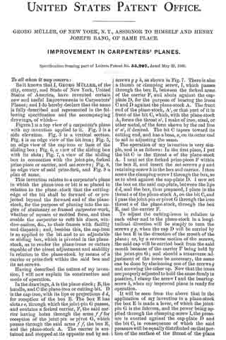
Figure 1 is a top view of a carpenter’s plane with my invention applied to it. Fig. 2 is a side elevation. Fig. 3 is a vertical section. Fig. 4 is an edge view of the bit-iron; Fig. 5, an edge view of the cap-iron or base of the sliding box; Fig. 6, a view of the sliding box with its slots; Fig. 7, a view of the sliding box in connection with the joint-pin, forked prize-piece or carrier, and set-screws; Fig. 8, an edge view of said prize-fork, and Fig. 9 a plan of same.
This invention relates to a carpenter’s plane in which the plane-iron or bit is so placed in relation to the plane-stock that the cutting-edge of the bit shall be forward of or projected beyond the forward end of the plane-stock, for the purpose of planing into the angles of stationary or framed carpenter-work, whether of square or molded form, and thus enable the carpenter to rent his doors, window-sashes, &c., to their frames with facility and dispatch; and, besides this, the cap-iron is so applied to the bit and to an adjustable or sliding box, which is pivoted in the plane-stock, as to render the plane-irons or cutters capable of the nicest adjustment and stability in relation to the plane-stock by means of a carrier or prize-fork within the said box and its set-screws.
Having described the nature of my invention, I will now explain its construction and mode of operation.
In the drawings, A is the plane-stock; B,the handle, and O the plane»iron or cutting-bit. D is the cap-iron, with its lips or projections d d, for reception of the box E. The box E has slots e e, through which the joint-pin G passes, and contains a forked carrier, F, the said carrier having holes through the arms f f for reception of the joint-pin or pivot G, which passes through the said arms f f, the box E, and the plane-stock A. The carrier is sustained and stopped at its opposite end by set-screws g g h, as shown in Fig. 7. There is also a thumb or clamping screw, I, which passes through the box E, between the forked arms of the carrier F, and abuts against the cap-plate D, for the purpose of bracing the irons G and D against the plane-stock A. The front end of the plane-stock, A’, or that part of it in front of the bit G, which, with the plane-stock A, forms the throat a’, I make of iron, steel, or other metal, of the form shown by the red line a’ a’, if desired. The bit C tapers toward its cutting end, and has a boss, x, on its outer end to aid in adjusting the same.
The operation of my invention is very simple, and is as follows: In the first place, I put the bit C in the throat a of the plane-stock A. I next set the forked prize-piece F within the box E, and insert the set-screws g g and retaining-screw It in the box and carrier. I then screw the clamping-screw I through the box, so as to abut against the cap-plate D. I now set the box on the said cap-plate, between the lips d d, and the box, thus prepared, I place in the throat ct of the plane-stock A, on the bit C, and I pass the joint-pin or pivot G through the iron throat a of the plane-stock, through the box E, and the carrier F.
To adjust the cutting-irons in relation to each other and to the plane-stock in a longitudinal direction will be simply to turn the screws g g, when the cap D will be carried by the box E in the direction of the mouth of the plane; or, by a reverse motion of the screws, the said cap will be carried back from the said mouth because of the carrier F being held by the joint-pin G; and should a transverse adjustment of the irons be necessary, the same can be done by slackening one of the screws g and screwing the other up. Now that the irons are properly adjusted to hold the same firmly in position, I clamp the screw I and the bearing-screw lt, when my improved plane is ready for operation.
It will be seen from the above that in the application of my invention to a plane-stock the box E is made a lever, of which the joint-pin G is the fulcrum, and the power being applied through the clamping-screw I, the pressure is exerted against the cap-plate D and the bit C, in consequence of which the said pressure will be equally distributed on that portion of the surface of the throat of the plane on which the bit C rests, and for which reason the plane-stock at its mouth will not become swollen or crushed down in rear of the bit and below the surface of the face of the plane, as is the case with the plane for which Letters Patent of the United States were granted to me on the 9th of October, 1865, in which the strain or pressure on the bit C, by means of the screw I, is brought to bear on the mouth of the plane-stock, crushing down the mouth of the plane in rear of the bit, thus rendering my previous invention inoperative, and to remedy this defect prompted me to produce my present invention, which I claim to be an improvement on the former.
Having described my invention, what I claim, and desire to secure by Letters Patent, is —
The sliding box E, with clamping-screw I, and the forked prize-piece F, in combination with the cap-plate D and bit C, together with placing the same in the throat a, or forward end of the plane-stock, substantially as and for the purposes set forth and described.
In testimony whereof I have hereunto set my signature.
GEORG MÜLLER.
Witnesses :
HENRY J. BANG,
A. NEILL.