
| PLEASE NOTE: The images presented on this page are of low resolution and, as a result, will not print out very well. If you wish to have higher resolution files then you may purchase them for only $2.95 per patent by using the "Buy Now" button below. All purchases are via PayPal. These files have all been cleaned up and digitally enhanced and are therefore suitable for printing, publication or framing. Each zip package contains all the images below (some packages may contain more), and purchased files can be downloaded immediately. |
UNITED STATES PATENT OFFICE.
_________________
JUSTUS A. TRAUT, OF NEW BRITAIN , CONNECTICUT.
SCRAPING-TOOL.
_________________
SPECIFICATION forming part of Letters Patent No. 553,879, dated February 4, 1896.
Application filed August 9, 1895. Serial No. 558,774. (No model.)
_________________
To all whom it may concern:
Be it known that I, JUSTUS A. TRAUT, a citizen of the United States, residing at New Britain, in the county of Hartford and State of Connecticut, have invented certain new and useful Improvements in Scraping-Tools, of which the following is a specification.
This invention relates to scraping-tools, adapted to be used for scraping or smoothing wooden surfaces — such, for instance, as surfaces of hard-wood or inlaid floors — and for other analogous purposes.
The object of my present invention is to furnish a simple, durable, and effective scraping-tool for the purpose above specified, and by means of which the scraping or smoothing of wooden surfaces may be executed with greater accuracy than is possible with the ordinary scraping-blade alone when used by hand, as heretofore common, and whereby the operation of scraping may be facilitated and rendered less tiresome to the workman.
In the operation of scraping wooden surfaces, as heretofore practiced, by means of a metal scraper-blade held in the hand, considerable difficulty has been experienced in holding the blade against the wooden surface with a uniform pressure from end to end of said blade, and to hold the blade at the required angle to secure good results and uniformity in work.
One of the chief objects of my present invention is to produce a scraping-tool that the ordinary workman may successfully manipulate and readily use in the operation of scraping or smoothing wooden surfaces, and to so construct and organize the parts of the scraping-tool that the scraper-blade may be adjusted and held at any desired angle relative to the plane of the surface being operated upon, and may be maintained at this angle during the entire operation without the exercise of skill upon the part of the workman, and whereby considerable power may be applied without material fatigue to the workman.
In the preferred form thereof herein shown and described my improved scraping-tool comprises a scraper-blade holder or frame embodying a clamp for holding a scraper-blade of said frame, a scraper-blade removably carried on said frame, a handle-bar or cross-bar preferably removably secured to the scraper-blade holder and having its ends projected beyond opposite ends of said holder, and a runner or tilting device preferably adjustably secured to the scraper-blade holder at an inclination to the scraper-blade holder and adapted for adjusting the blade to any desired angle relatively to any surface it is desired to operate upon.
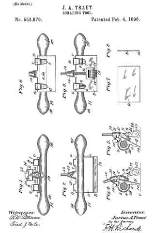
In the drawings accompanying and forming part of this specification, Figure 1 is a plan view of a scraping-tool embodying my present invention. Fig. 2 is a front view of said scraper-tool as seen from the left hand in Fig. 4. Fig. 3 is a rear view of said scraper-tool as seen from the right hand in Fig. 4. Figs. 4 and 5 are end views, respectively, of the scraper-tool as seen from the right hand in Fig. 3 and showing, respectively, two different positions of the holder and scraper-blade relatively to a surface upon which the tool is supported. Fig. 6 is a rear view, similar to Fig. 3, of the scraper-blade holder and handle-bar with the adjusting-support, scraper-blade, and clamp-screws removed. Figs. 7 and 3 are side and edge views, respectively, of the scraper-blade detached.
Similar characters represent like parts in all the figures of the drawings.
The scraper-blade holder (designated in a general way by B) will usually consist of a rigid metal bearing-plate 2, having a plane inner face, which forms a bearing for the scraper-blade, and having a recess 3 in the outer face thereof, which forms a seat for the handle-bar H, which is seated in said recess, and is removably secured in place by means of a screw 4, which extends through the bearing-plate 2, as shown most clearly in Fig. 6 of the drawings.
The scraper-blade holder embodies a blade-clamp, which, in the preferred form thereof herein shown, comprises two depending clamp-arms 6 and 7, which are preferably formed integrally with the bearing-plate 2, one near each side edge of said plate, as shown most clearly in Figs. 1 to 6, inclusive, of the drawings. These depending arms overlap the plate 2 near the upper edge thereof, and have their inner bearing-faces slightly remote from, and in parallelism with, the adjacent bearing-face of the plate 2, as will be understood by reference to Figs. 4 and 5 of the drawings, the connecting portions 6’ and 7’, between the upper edge of the guiding-plate 2 and arms 6 and 7, forming abutments against which the upper edge of the scraper-blade S may abut for holding said scraper-blade against accidental vertical movement when in place between the depending clamp-arms and the bearing-face of the plate 2.
If desired, the clamp-arms 6 and 7 may be made resilient, and impinge the scraper-blade sufficiently to hold the same in place in the holder without the employment of clamp-screws; but for the purpose of positively holding the scraper-blade S in the holder B, I have shown the clamp-arms 6 and 7, provided with set-screws 8 and 9, respectively, which extend through screw-threaded holes in said clamp-arms, as illustrated in Figs. 4 and 5 in dotted line, and bear at their inner ends against the face of the scraper-blade S.
I do not limit myself to the particular construction of holder illustrated in the drawings, as the construction thereof may be modified within the scope and limits of my invention.
The scraper-blade S, which will usually be a flat sheet-metal plate, will preferably be slightly oblong in form, and will have the scraping edge beveled, as shown at 10, said blade being slightly greater in width transversely of its scraping edge than the distance between the abutments 6′ and 7′ and the lower edge of the bearing-plate 2 of the holder B, so that the scraping edge of the blade will project slightly beyond the lower edge of said holder.
As a convenient means for supporting the holder H and the blade S in the proper working position relatively to the surface (designated by the horizontal line C, Figs. 4 and 5) to be operated upon, and with the scraper-blade at the desired inclination or angle relatively to said surface, I have provided a support or runner, (designated in a general way by R,) which will preferably be adjustably secured to the scraper-blade holder B, so as to be capable of adjustment transversely of the plane of the scraping edge of the scraper-blade. This support or runner R, which may be referred to herein as the “adjusting-support,” is herein shown consisting of a rod or bar 12, carrying a roller 13 at the lower end thereof, adapted for resting upon the surface being scraped. This roller is shown carried between arms 14 and 14’ at the lower end of the bar 12, as shown most clearly in Figs. 1, 3, 4, and 5 of the drawings.
As a convenient means for adjustably securing the adjusting-support to the holder H at the proper inclination relatively to said holder and the blade carried thereby, I have shown the holder with a boss or bearing 15, formed at the upper edge thereof, approximately midway between the two clamp-arms 6 and 7, as will be understood by reference to Figs. 1 to 6, inclusive, of the drawings. This boss has a recess 16 formed therethrough, the axis of which intersects the plane of the bearing-face of the plate 2 of the holder, which recess is adapted to receive and permit a longitudinal sliding movement of the bar 12 of the adjusting-support. The degree of inclination of the recess 16 relatively to the plane of the scraper-blade carried in the holder will, of course, depend largely upon the requirements of the trade, the angle being herein shown as approximately one of thirty degrees, which I have found most convenient for general use.
As a means for adjustably securing the adjusting-support R in the bearing 15, and as a means for holding the same against rotation, I have shown the bar 12 of said support having one flat portion 18, and have shown the recess 16 of a cross-sectional shape corresponding to the cross-sectional shape of said bar, the bar being held in adjustable position in the bearing preferably by means of a set-screw 19, which extends through the boss or bearing 15 and bears at its inner end against the flat side of the bar 12 of said adjusting-support.
It will be obvious that the means for adjustably securing the adjusting-support R to the holder and the particular construction of said means and support may be variously modided without departure from my invention.
The handle-bar H is herein shown extended beyond the side of the holder B and provided with handles or knobs 20 and 20′ at opposite ends thereof, which may be grasped by the workman when manipulating a scraper-tool. This handle is made removable, so as to enable the workman to detach the same from the scraper-blade holder when it is desired to use the tool for scraping corners, &c.
When it is desired to change the inclination of the scraper-blade S relatively to a surface, as C, it is simply necessary to loosen the set-screw 19, which clamps the bar 12 of the adjusting-support R, and slide said bar upward or downward longitudinally in the bearing 15, and secure the same in adjusted position by said set-screw 19, which will increase or decrease the angle of the scraper blade and holder relatively to said surface, as will readily be understood by comparison of Figs. at and 5 of the drawings.
Having thus described my invention, I claim —
1. A scraping-tool comprehending a scraper-blade holder and a runner adjustably connected together at their upper ends for adjustment, one relatively to the other, in an intersecting plane, and diverging from their points of connection toward their opposite, lower ends; and a scraper-blade removably carried by the holder with its scraping edge extending below the lower end of the holder.
2. A scraping-tool comprehending a scraper-blade holder and a runner adjustably connected together at their upper ends for adjustment, one relatively to the other, in an intersecting plane, and diverging from their points of connection toward their opposite, lower ends; a scraper-blade removably carried by the holder with its scraping edge extending below the lower end of the holder; and a handle-bar secured to the holder with its longitudinal axis in a plane substantially parallel to the plane of the scraping edge of the scraper-blade.
3. In a scraping-tool, the combination with a scraper-blade holder having a scraper-blade supporting-face, substantially as described, and having an inclined transverse bearing at the upper end thereof; and an adjusting-support having a member adjustably carried in said bearing at an inclination to the plane of the supporting-face of said holder, substantially as described.
4. The combination with a scraper-blade holder having a scraper-blade clamp, and also having an inclined fixed bearing at the upper end thereof; of a scraper removably secured to said holder; and an adjusting-support having a bar shiftably carried in the bearing on the scraper-blade holder at a fixed inclination to the plane of the scraper-blade, and also having its lower end remote from, and in alignment with, the scraping edge of the scraper-blade, whereby the scraper-blade may be supported on the surface at an inclination to said surface, and whereby the degree of said inclination may be changed.
5. In a scraping-tool, the combination of a scraper-blade holder having a scraper-blade supporting-face, substantially as described, and also having a fixed bearing at the upper end thereof, which is inclined to the plane of the supporting-face; a supporting-bar adjustably carried in the bearing on said holders with its longitudinal axis intersecting, and at an inclination to, the plane of the supporting-face and scraper-blade holder; and a set-screw extending through one side of said bearing, and engaging the supporting-bar for holding said bar in adjusted position relatively to the holder, substantially as described.
6. In a scraping-tool, the combination of a scraper-blade holder having a scraper-blade supporting-face, substantially as described, and also having a non-circular supporting-bar receiving bearing at the upper edge thereof, the axis of which is transversely disposed and inclined relatively, to the scraper-blade holder; and a cross-sectional, non-circular supporting-bar shiftably carried in said bearing with its axis at an inclination to the plane of the supporting-face of the scraper-blade holder, and having a roller at the lower end thereof.
7. In a scraping-tool, the combination of a scraper-blade holder having a scraper-blade supporting-face, substantially as described, and also having an inclined transverse bearing at the upper edge thereof; a supporting-bar shiftably supported in said bearing at an inclination to the plane of the supporting-face of said holder; means for clamping the supporting-bar in adjusted position in said bearing; a roller carried at the lower end of said supporting-bar remote from the lower edge of the holder; a scraper-blade removably supported upon the supporting-face of the holder; a clamp carried by the holder and engaging the scraper-blade; and a handle-bar removably carried on a scraper-blade holder with its longitudinal axis in parallelism with the scraping edge of the scraper-blade.
8. A scraping-tool, comprising a scraper-blade holder and an adjusting-support adjustably secured together at their upper ends at a fixed inclination relatively to one another, and with their lower edges in alignment with, and remote from, each other; a scraper-blade removably carried by the scraper-blade holder; means for adjustably clamping the scraper-blade upon said holder; and a handle-bar removably secured to the scraper-blade-holder with its longitudinal axis in parallelism with the scraping edge of the scraper-blade.
JUSTUS A. TRAUT.
Witnesses:
CHAS. B. STANLEY,
W. J. WORAM.