
| PLEASE NOTE: The images presented on this page are of low resolution and, as a result, will not print out very well. If you wish to have higher resolution files then you may purchase them for only $2.95 per patent by using the "Buy Now" button below. All purchases are via PayPal. These files have all been cleaned up and digitally enhanced and are therefore suitable for printing, publication or framing. Each zip package contains all the images below (some packages may contain more), and purchased files can be downloaded immediately. |

UNITED STATES PATENT OFFICE.
_________________
JUSTUS A. TRAUT, OF NEW BRITAIN, CONNECTICUT.
CORE-BOX PLANE.
_________________
SPECIFICATION forming part of Letters Patent No. 556,114, dated March 10, 1896.
Application filed September 18, 1895. Serial No. 562,829. (No model.)
_________________
To all whom it may concern:
Be it known that I, JUSTUS A. TRAUT, a citizen of the United States, residing at New Britain, in the county of Hartford and State of Connecticut, have invented certain new and useful Improvements in Core-Box Planes, of which the following is a specification.
This invention relates to planes adapted for planing concaved surfaces of different areas, and more particularly designated as a “core-box” plane; and the object of the invention is to provide a plane having supplemental side extension-plates, whereby each or both sides of the stock can be extended to different widths and whereby the plane is rendered serviceable for finishing and planing core-boxes of a wide range of sizes, and also for use in connection with other concaved surfaces.
A further object of the invention is to provide a fastening means whereby the supplemental side extension-plates can be reversed and interchanged, or whereby they can all be secured to one side of the stock, and which fastening means is simple and easily and quickly manipulated.
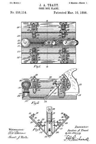
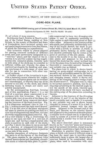
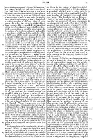
In the accompanying drawings, forming part of this specification, Figure 1 is a top view of a core-box plane constructed in accordance with this invention. Fig. 2 is an interior side view of one side of the plane, the other side thereof being removed and showing the juncture of the stock in section. Fig. 3 is a transverse sectional view in line a a, Fig. 1, looking toward the right hand thereof. Fig. 4 is an end view of the plane and shows same in position for planing one-half of a the core-box of comparatively-small size, and also shows the supplemental plates removed. Fig. 5 is a view similar to Fig. 4, illustrating the plane in use upon one-half of a core-box of larger size and having a supplemental side plate in position on each side of the stock; and Fig. 6 shows the plane in use on one-half of a core-box of comparatively-large size with the supplemental side plates in position on one side of the stock.
Similar characters of reference designate like parts in all the figures of the drawings.
The plane consists, in the preferred form thereof herein shown and described, of a suitable stock or relatively-thin plate 10, preferably constructed to form two diverging side plates 11 and 12, preferably extending at right angles to each other and joined at their inner edges. Adjacent to the juncture of the side plates, and preferably substantially midway of the length thereof, the stock is provided with a mouth or mortise 13, which is preferably shown forming an acute angle, and likewise preferably has its vertex at the point of juncture of the side plates. Adjacent to the mouth 13 on the interior of the side plates and adjacent to the juncture thereof the stock has the usual inclined bed 14 for the plane-iron, formed either integrally therewith or removably secured thereon in any suitable way as desired.
The plane-iron 15, which is shown herein having an acute-angled cutting-edge, is removably and adjustably seated on the bed 14; and secured thereto by the usual fastening and clamping means, which is shown consisting of the clamping plate or wedge 16 and the thumb-screw 17. The plane-iron 15, when in its normal operative position, has its cutting-edge projecting at the desired angle below the mouth of the stock, whereby each side plate of the stock will have one-half of the cutting-edge of the plane-iron extending therein.
Adjacent to the juncture of the diverging side plates 11 and 12 on the interior of the stock a suitable toat or handle 13 is secured in any suitable way and is shown herein clamped by means of a screw 20 to a bed 19, preferably formed integral with the side plates. Adjacent to the forward end of the stock, and likewise on the interior thereof and adjacent to the juncture of the side plates, a suitable knob or hand-rest 21 is likewise secured by means of a screw 22 and bed 23 in substantially a similar way to that of securing the toat 18.
The above-described plane is commonly known as the “core-box” plane and forms no part of my present invention, except in so far as the plane constitutes a basis for the same.
Heretofore in practice when necessary to plane or finish core-boxes of different sizes it has been the usual case to provide a plane sufficiently large to plane the largest size of core-box desired to be constructed, which plane, when used in connection with core-boxes having comparatively-small diameters, is extremely clumsy to use, and when desirable to obviate this disadvantage it has been the usual practice to construct core-box planes of different sizes for work on different sizes of core-boxes, which is not only expensive but a great disadvantage when it is desired to make a number of different sizes of such boxes. In order, therefore, to obviate these disadvantages I have provided, in connection with a core-box plane of any suitable and desired construction, a suitable attachment in the nature of a guide or rest and which guide or rest is adjustable and attachable to either or both sides of the stock, as desired, and in the preferred form thereof herein shown and described preferably consists of a supplemental extension plate or plates adapted to be secured to the stock with one of its edges in parallelism with the free edge of one of the side plates forming the stock by means of a suitable fastening device. In the construction shown two of these supplemental extension-plates are provided and designated in a general way by 25 and 35. These plates may be constructed of any desired thickness and width, but are preferably constructed of about the same width as the side plates forming the stock and of sufficient thickness to permit the outer side face thereof to be in alignment with the outer side face of the adjoining side plate of the stock when the supplemental plates are in position on the stock. These plates are likewise constructed of any suitable material, but preferably of the same material as the stock, which is usually of metal, and each plate is adapted to rest on the free edge of one of the respective stock-plates 11 and 12, with one of its edges in parallelism therewith, or on the free edge of a supplemental side plate 25 or 35. As a means for securing these supplemental extension side plates in position, the side plates 11 and 12 of the stock on the interior thereof are provided with any desired number of socketed brackets 26, preferably formed integral with such side plates, and in the construction shown each side plate of the stock is provided with two of these brackets 26, one near each end thereof. These brackets are provided with clamping devices projecting through the walls and intersecting the sockets thereof at right angles thereto, and in the form shown these clamping devices are in the nature of set-screws 27, working in threaded apertures in the walls of the brackets. Removably secured in each of these socketed brackets is a bolt or bar 23, having a part thereof projecting therefrom in a plane parallel with the plane of inclination of its adjacent stock side plate.
Each supplemental extension side plate has secured thereto by any suitable means, such as by rivets, or integrally formed therewith, if desired, suitable fastening means for the bolts 28, which fastening means is preferably shown herein consisting of brackets 36. These brackets 36 are in the nature of double-socketed brackets, and are provided with bolt openings or sockets 37 adapted to receive the bolts 28, and each extension-plate preferably has the same number of brackets 36 as each stock side plate. The brackets are so disposed, relatively to each supplemental side plate, that the two sockets 37 of each bracket are in alignment with each other and with the socket of the companion bracket 26 on the stock side plates when said supplemental extension-plates are in position relatively to the side plates of the stock, and each bracket has a socket 37 adjacent to each longitudinal edge of the plate and in parallelism with the side face thereof, whereby the plates are interchangeable and reversible. These brackets are provided with clamping devices 33, one adjacent to each socket thereof, substantially similar to the clamping devices of the stock side plates and secured therein in substantially the same way, whereby either edge of a supplemental plate can rest on the free edge of the stock side plate and be secured in such position by the clamping device 38 and bolt or stud 28.
In the use of this improved core-box plane when it is desired to plane or finish a core-box of comparatively-small size the supplemental side extension-plates 25 and 35 are removed and the plane used in the ordinary way. (See Fig. 4.) When, however, a core-box of larger size is to be planed, the supplemental side plates are secured in position, one to each side of the stock, by means of the bolts 28 and clamping devices 27 and adjacent clamping devices 38, (see Fig. 5, for instance,) whereby a concaved surface of comparatively-large area can be planed, the supplemental side entension-plates 25 and 35 forming a rest or guiding means for each side of the plane. When, however, a core-box of very large size is to be planed, one of the supplemental plates, as 25, together with its bolts 28, is removed from one side of the stock and the bolts slipped into the upper sockets 37 of the brackets 36 adjacent to the upper edge of the other side-plate 35, and the side plate 25 then secured in position by means of the clamping devices 38 adjacent to such upper sockets of the plate 35, whereby the supplemental side extension-plates of the plane form a rest or guiding means when the same is used to plane or finish the core-box concavity in a manner similar to that shown. in Fig. 6. Any number of these supplemental plates may be provided with each stock, whereby many different sizes of core-boxes can be finished or planed with one plane. By means of this improved construction of supplemental extension-plates the same are interchangeable with each other, whereby they can be used on either side of the stock and also reversible relatively to the stock-plates — that is to say, either longitudinal edge of each extension-plate can be secured in position contiguous to the longitudinal edges of the stock-plates — whereby one or both sides of the stock can be built up of any desired width in accordance with the number of plates used and the requirements of the plane. Moreover, if it is desired to increase the width of the sides of the plane, when one or more extension-plates are secured on the stock, without attaching an extra plate, the bolts can be made of such length that the supplemental plates can be adjusted relatively to the side plates of the stock or to their adjoining supplemental plates to leave a space between their adjoining edges, whereby the necessity of attaching an extra plate for a slight increase of width is obviated.
By means of my improved plane it will be obvious that when a small core-box is to be finished the plane can be used with the stock simply formed by the two side plates, which side plates, in the construction shown are comparatively light and of very much less width than in the ordinary construction of stock side plates, whereby in the use of the same upon comparatively-small core-boxes the plane is light and easy to handle.
Having thus described my invention, what I claim is —
l. In a plane of the class specified, the combination of a stock constructed of two diverging plates; each of said plates having a pair of socketed brackets; a plurality of removable, interchangeable, and reversible extension-plates, each of said extension-plates having a pair of double-socketed brackets fixed thereto, the two sockets of each bracket being in alignment with each other and with a socketed bracket of one of the stock-plates, and each bracket of an extension-plate having a socket adjacent to each of its edges, whereby the extension-plates are interchangeable with each other and reversible relatively to the stock-plates, and whereby either longitudinal edge of an extension-plate can be secured in position contiguous to a stock-plate; bars or bolts removable with and independently of said extension-plates for securing said plates in position relatively to each other and to one side of the stock, to thereby increase the width of that side of said stock independently of the other side thereof, or to secure one or more of said plates to, and thereby increase the width of, each side of said stock; and fastening devices for securing said bars or bolts in position.
2. In a plane of the class specified, the combination of a stock constructed of two diverging side plates disposed at right angles to each other, and having a mouth at the juncture of said plates; a plane-iron in position adjacent to said mouth, and having its cutting-edge adapted to extend therethrough; each of said stock-plates having a pair of single-socketed brackets; a pair of removable, interchangeable, and reversible extension-plates, each of said extension-plates having a pair of double-socketed brackets fixed thereto, the two sockets of each bracket being in alignment with each other and with a socketed bracket of one of the stock-plates, and each bracket of an extension-plate having a socket adjacent to each of its edges, whereby the plates are interchangeable with each other and reversible relatively to the stock-plates, and whereby either longitudinal edge of an extension-plate can be secured in position contiguous to a stock-plate; bars or bolts removable with and independently of said extension-plates for securing said plates in position relatively to each other and to one side of the stock, to thereby increase the width of that side of said stock independently of the other side thereof, or to secure one or more of said plates to, and thereby increase the width of, each side of said stock; and fastening devices for securing said bars or bolts in position.
JUSTUS A. TRAUT.
Witnesses:
F. N. STANLEY,
H. S. WALTER.