| PLEASE NOTE: The images presented on this page are of low resolution and, as a result, will not print out very well. If you wish to have higher resolution files then you may purchase them for only $2.95 per patent by using the "Buy Now" button below. All purchases are via PayPal. These files have all been cleaned up and digitally enhanced and are therefore suitable for printing, publication or framing. Each zip package contains all the images below (some packages may contain more), and purchased files can be downloaded immediately. |
UNITED STATES PATENT OFFICE.
_________________
ALBERT A. PAGE, OF EAST HAVEN, CONNECTICUT, ASSIGNOR TO
THE SARGENT & COMPANY, OF NEW HAVEN, CONNECTICUT.
PLANE.
_________________
SPECIFICATION forming part of Letters Patent No. 585,889, dated July 6, 1897.
Application filed May 16, 1896. Serial No. 591,46. (No model.)
_________________
To all whom it may concern:
Be it known that I, ALBERT A. PAGE, a citizen of the United States, and a resident of the town of East Haven, county of New Haven, in the State of Connecticut, have invented a new and useful Improvement in Planes, fully set forth and described in the following specification, taken in connection with the accompanying drawings, which form a part thereof, and in which —
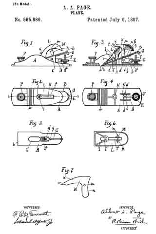
Figure 1 represents a side elevation of a plane embodying my invention; Fig. 2, a top view of the same; Fig. 3, a vertical longitudinal section on the line 3 3 of Fig. 2; Fig. A, a top view of the frame; Fig. 5, a bottom view of the plane iron or bit, Fig. 6, a corresponding view of the clamping-cap; Fig. 7, a detail of the clamping-lever.
In all the figures similar letters of reference represent like parts.
This invention relates to hand-planes; and it consists in a novel construction of parts, which when assembled produce a simple device easily regulated or adjusted.
The invention refers more particularly to an improved method of locking the plane iron or bit between the frog and the clamping-cap by means of a lever pivoted in said clamping-cap to swing vertically beyond its dead-center, as set forth and described, together with other improvements, hereinafter.
Referring to the drawings for the more particular description, A represents the stock or frame, and a the throat thereof.
B is the plane iron or bit, with b its cutting edge, the bit having a longitudinal slot b’, extending central therein, and on the under side adjacent to said slot b’ and extending lengthwise therefrom a series of teeth b2.
Mounted on the frame A is a frog C, which consists of two parallel vertical plates with diagonal upper edges, the plates being united by a block c, slotted vertically a short distance downward from its top. In the slot of the block c is pivoted by means of the pin d’ an adjusting-lever D, having on its upper side a number of teeth d, which extend slightly above the level of the frog C. The free end of said lever has a horizontal slot d2, of sufficient width to receive the edge of the adjusting-nut E, threaded to run on the vertical screw F, rigidly mounted near the end of the frame A. The edge of this nut E being knurled, it may be easily screwed up and down, and with the movement of the nut the engagement of the slot d2 of the lever D raises and lowers the free end thereof, which swings the teeth d forward or back. As the bit B is adapted to rest on the frog C, the teeth d of the adjusting-lever D engage with the teeth b2 on the under side of the bit, and the movement of the teeth produced by the adjusting-nut E on screw F is communicated to the bit, the edge of which is then forced deeper into or withdrawn from the throat a of the frame A.
Pivoted by a screw g to the under side of the bit B adjacent to the teeth b2 is a forked lever G, the fork g’ of the lever lying across the teeth b2 and the other end projecting beyond the end of the bit. This lever G is capable of swinging in a horizontal plane, and when the bit is fitted on the frog C the fork g’ is adapted to embrace the teeth d on the adjusting-lever D. When the fork g’ is thus engaged with the teeth d, which are secure against any transverse movement, the swinging of the lever G will tend to force the upper end of the bit to one side or the other, and as the bit is practically pivoted by the screw I, described hereinafter, the swinging will give a side adjustment or equalizing movement to square the cutting edge b.
Between the throat a and the frog C on the frame A is mounted the cylindrical block H, centrally bored and having a diagonal upper end corresponding to the edge of the frog C. The central bore is internally threaded for a screw I, over which the slot b’ of the bit is adapted to fit.
A clamping-cap L, the rear end of which is rounded, as shown, Figs. 1 and 3, has in its forward part a slot l, corresponding to the diameter of the head of the screw I and extending rearwardly from the slot l, a secondary slot l’ corresponding to the diameter of the shank of the screw I. A rectangular slot l2 extends centrally in the cap L, and on either side near its rear end are depending ears M. Pivoted between the ears M, by the pin m at its elbow, is a substantially right-angled lever N. One arm n of this lever is rounded to bear on the upper side of the bit B, as hereinafter described, and the other arm n’ is formed to correspond with the upper side of the clamping-cap L, as shown in Figs. 1, 3, and 7, the extreme end being flattened and widened to act as a thumb-piece, Fig. 2.
When the clamping-cap is placed over the bit B, the slot l being fitted over the screw I and the cap forced forward so that the screw is engaged in the slot l’, the right-angled lever H is used as a clamp to hold the parts together and rigidly secure them in place.
Upon the forward movement of the arm n’ the other arm n bites against the bit B, and the tendency is to force the clamping-cap L forward into closer engagement with screw I, Fig. 3.
The slight elasticity in the cast metal allows the clamping-cap to be raised as the arm n of the clamp passes the perpendicular, so that when in the position shown in Fig. 1 the parts are securely locked. The screw I may be raised or lowered to secure the right adjustment of the clamping-cap and clamp. The forward position of the clamp when the parts of the plane are locked and its conformity with the surface of the clam ping-cap makes a smooth handle and prevents the hand of the operator from being caught on the clamp when the plane is in use.
A finger-knob P is shown in the forward part of the frame beyond the throat, which may also serve as an adjusting-screw for a sliding throat-piece, as is often the case.
Having now described my invention, what I claim, and desire to secure by Letters Patent, is —
In a plane, the combination with the frame; of the bit; a support on the frame for the bit; a locking device mounted on the frame, a clamping-cap above the bit, forming the main handle portion of the plane, and having its forward end adapted to engage with said locking device to lock the forward end of the bit, while its rear end is provided with a longitudinal slot; a substantially right-angled clamp pivoted in said clamping-cap, with one arm adapted to swing forward in said longitudinal slot, and the other arm to bear on the bit and lock; the rear of the same, when the forwardly-swinging arm has assumed a position in alinement with the main portion of said clamping-cap; and means on said clamp for disengaging it from its locked position, substantially as described.
In witness whereof I have hereunto set my hand, at New Haven, in the county of New Haven, State of Connecticut, this 11th day of May, 1896.
ALBERT A. PAGE.
Witnesses:
WILLIAM T. COOKE,
CHARLES L. BALDWIN.


