
| PLEASE NOTE: The images presented on this page are of low resolution and, as a result, will not print out very well. If you wish to have higher resolution files then you may purchase them for only $2.95 per patent by using the "Buy Now" button below. All purchases are via PayPal. These files have all been cleaned up and digitally enhanced and are therefore suitable for printing, publication or framing. Each zip package contains all the images below (some packages may contain more), and purchased files can be downloaded immediately. |


UNITED STATES PATENT OFFICE.
_________________
JUSTUS A. TRAUT, OF NEW BRITAIN, CONNECTICUT.
PLANE.
_________________
SPECIFICATION forming part of Letters Patent No. 591,662, dated October 12, 1897.
Application filed July 6, 1897. Serial No. 643,617. (No model.)
_________________
To all whom it may concern:
Be it known that I, JUSTUS A. TRAUT, a citizen of the United States, residing in New Britain, in the county of Hartford and State of Connecticut, have invented certain new and useful Improvements in Planes, of which the following is a specification.
This invention relates to planes, and it comprehends, essentially, a stock or body portion and a mouthpiece bodily adjustable on the stock.
In the form of the invention herein described the stock or body portion of the plane is constructed of wood, and the mouthpiece or plate is made of metal and is bodily adjustable on the stock or body portion in a direction transverse to the line of working movement of the plane, so that the sole of the latter can be dressed down to remove any unevenness in its surface from constant use and so that the mouthpiece or plate can be adjusted to compensate for the variation until its working face is flush with the sole or under surface of the plane-body.
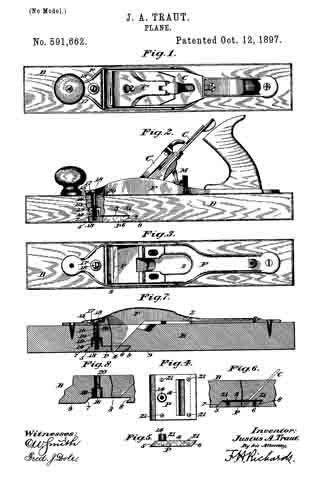
In the drawings accompanying and forming part of this specification, Figure 1 is a plan view of a smooth plane embodying my present improvements. Fig. 2 is a side elevation of the same. Fig. 3 is a plan view of the plane with the cutter and its holding and operating parts removed. Fig. 4 is a plan view of the adjustable mouthpiece. Fig. 5 is a side elevation of the same. Fig. 6 is a longitudinal central section of a fragment of the plane, showing the adjustable mouthpiece therein. Fig. 7 is a longitudinal central section of a plane, representing a modification of the mouthpiece; and Fig. 8 is a longitudinal central section of a fragment of the plane-body illustrated in Fig. 7.
Similar characters designate like parts in all the figures of the drawings.
The stock or body of the plane represented in the fhawings is designated by B, and it is constructed, preferably, of wood. A metallic frame for carrying the usual cutter or plane-iron is designated by F, and is fastened near its opposite ends to the upper face of the stock B. The cutter or plane-iron is designated by C, and its clamping-lever by C’, and the operating mechanism for the cutter is designated by M, and as these parts are mounted in the usual manner in the loop or open portion 2 of the frame and are of common construction a detailed description thereof is deemed unnecessary.
My improved plane comprehends a stock or body portion and a mouthpiece bodily adjustable thereon, said mouthpiece consisting in the present instance of a plate adjustable in a direction transverse to the line of working movement of the plane.
The mouthpiece of the plane is designated by P, and it is represented consisting of a rectangular metallic plate set within a mortise or cavity 3, formed in the bottom or sole of the stock or body portion B. The mouthpiece or plate P has near its rear end the elongated mouth or slot 4, through which the cutter or plane-iron C may extend. The front and rear ends of the mouthpiece are beveled or inclined and fit against the similarly beveled or inclined walls 7 and 8 of the mortise, the latter being of a depth exceeding that of the mouthpiece P, as represented, respectively, in Figs. 2 and 6.
By reason of the construction just described the mouthpiece P can be set farther into the mortise 3 and its under face maintained flush with the sole or bottom surface 9 of the plane-body.
On an inspection of Fig. 6 it will be observed that the bevels or inclinations 5 and 6 on the front and rear ends, respectively, of the mouthpiece P correspond substantially with the inclination of the cutter or plane-iron C, so that if said mouthpiece be set in to a greater or less depth in the plane body or stock it will be adjusted in the direction of the length of the plane-iron and also of the stock or body portion, so as to maintain the proper working relation between the lower or cutting end of the said plane-iron and the mouth-piece.
The mouthpiece P is preferably held to the body portion by a screw passing through the body or stock B, the lower threaded end of which engages the internal threads 13 on the boss or hub 14, near the forward end of the mouthpiece. The screw extends through the slot or hole 15 in the frame F and the opening or aperture 16 in the body or stock B, a washer 17, serving its usual purpose, being placed between the screw-head 18 and the frame F. The opening 16 in the body portion B, which communicates with the mortise 3, is of different sizes or diameters, the wider or larger portion 19 being adapted to receive the internally-threaded boss 14 of the mouthpiece and its diameter exceeding that of the boss, so that as the mouthpiece is moved up or down in its mortise or recess in the body portion the holding-screw 10 can be properly seated in the boss without affecting the proper relation of the several parts, as will be apparent. For this purpose also the diameters of the reduced or narrower portion 20 of the aperature 16 and of the slot 15 in the cutter-carrying frame exceed that of the screw, so that the latter can be moved forward or backward in accordance with the adjustment of the mouthpiece.
It will be remembered that the mortise or recess 3 is preferably made deeper than the mouthpiece or plate P, and the mouthpiece or plate is provided with adjusting means adapted to bear against the roof of the mortise, said adjusting means consisting of a plurality of screws, as 21, disposed on the upper face of the mouthpiece, as shown in Fig. 4. The upper or slotted ends of the screws are adapted to bear against the roof of the mortise 3, so that the mouthpiece can be nicely fitted in its seat with its lower face true or flush with the sole of the plane.
In Fig. 2 the mouthpiece and the several cooperating parts are shown assembled in the plane-body. Let it be assumed that it is necessary to dress off the sole of the plane-body. In this event the plate-holding screw 10 is removed, so that the mouthpiece or plate P can be taken from its mortise or recess 3. The sole of the plane is then resurfaced. The several adjusting-screws are then driven slightly farther in their seats in the mouthpiece and the latter inserted in the mortise. If the lower face of the mouthpiece is flush with the sole, the holding-screw 10 will be inserted in place; if not, said mouthpice will be removed and the adjusting-screws will be driven farther into their seats, and this manipulation of the adjusting-screws will continue until the under face of the mouthpiece is alined with the sole; but it will be evident that it is but the work of a moment to properly adjust the mouthpiece. When the same is adjusted, the holding-screw 10 is placed in position.
In Figs. 7 and 8 I have illustrated a modified form of the invention wherein the adjusting-screws are dispensed with, the construction otherwise being similar to the preferred form. When it is desired to adjust the mouthpiece shown in Figs. 7 and 8, it is simply necessary to cut away the upper surface or roof of the mortise to correspond with the dressing off of the sole.
It will be observed on an inspection of Figs. 2 and 7 that the mouthpiece P constitutes also a clamping or resistance plate for assisting in holding the cutter-carrying frame in place on the stock, and the holding-screw 10, which is seated in said mouthpiece, also constitutes a part of the frame-securing means, as has been described.
By means of my present improvements the plane or under surface thereof may be readily repaired from time to time by the user, so as to maintain the implement in perfect working order for a long period of time, hence materially prolonging its life and reducing the cost of the tool proportionately to the amount of work done. At the same time the mouthpiece of the wood body being adjustable, as hereinbefore set forth, said mouthpiece is maintained in proper form relatively to the stock and to the cutter regardless of the extent to which the bottom or the sole of the plane may be cut away in resurfacing.
Having described my invention, I claim —
1. A plane comprising a stock having a mortise in its under side, the front and rear walls of which are beveled, said stock also having an aperture extending therefrom and communicating with the mortise; a mouthpiece having its ends beveled to conform to the walls of the mortise; screws carried by the mouthpiece and bearing against the roof of the mortise; and a holding-screw pressing through and of less diameter than the aperture in the stock and having its lower end in threaded engagement with the mouthpiece.
2. A plane comprising a stock having a mortise the front and rear walls of which are beveled, and also having an aperture extending entirely through the stock and communicating with the mortise, said aperture being of different sizes; a mouthpiece bodily adjustable in, and of less depth than, the mortise and furnished with a threaded boss or stud of a less diameter than the wider portion of said aperture, said mouthpiece having its opposite ends beveled to correspond with the beveled surface of the front and rear walls of the mortise; a series of screws threaded in the mouthpiece, the heads of the screws bearing against the roof of the mortise; and a holding-screw passing through the aperture in the stock from the upper side, and having its lower threaded end in engagement with said boss, the screw being of a less diameter than the narrower portion of the aperture through which it passes.
JUSTUS A. TRAUT.
Witnesses:
H. S. WALTER,
W. J. WORAM.