
| PLEASE NOTE: The images presented on this page are of low resolution and, as a result, will not print out very well. If you wish to have higher resolution files then you may purchase them for only $2.95 per patent by using the "Buy Now" button below. All purchases are via PayPal. These files have all been cleaned up and digitally enhanced and are therefore suitable for printing, publication or framing. Each zip package contains all the images below (some packages may contain more), and purchased files can be downloaded immediately. |
UNITED STATES PATENT OFFICE.
_________________
JOHN N. SCHNEIDER, OF MENDOTA, ILLINOIS.
PLANE.
_________________
SPECIFICATION forming part of Letters Patent No. 597,622, dated January 18, 1898.
Application filed January 14, 1897. Serial No. 619,148. (No model.)
_________________
To all whom it may concern:
Be it known that I, JOHN N. SCHNEIDER, a citizen of the United States, residing at Mendota, in the county of La Salle and State of Illinois, have invented certain new and useful Improvements in Planes; and I do hereby declare the following to be a full, clear, and exact description of the invention, such as will enable others skilled in the art to which it appertains to make and use the same.
My invention relates to improvements in hand-planes, and has for its object the production of an improved plane the bit of which will be autornatically retired from its operative position during the back stroke of the plane.
A further object is the production of novel mechanism for the adjustment of the bit which may be regulated while the plane is being moved over the surface to be planed and without removing the hand from the handle.
Subordinate to these general objects a still further object of my invention is to provide certain novel and efficient mechanism for accomplishing the various attachments of the several parts of the device, as will hereinafter be made apparent.
To the accomplishment of the objects stated my invention consists in providing a plane-stock with a pivoted bit-stock and with a handle designed by its rotation to regulate the adjustment of the bit-stock and to automatically throw the bit into its operative or inoperative positions as the pressure exerted upon the handle is directed to propel or retract the plane.
In order that the utility of the invention may be readily understood, it may be remarked that in the usual manipulation of devices of this general character the backward movement or stroke of the plane is accompanied by the abrasion of the bit, which gradually turns the cutting edge and necessitates an additional pressure upon the plane in order to secure a proper bite upon the material to be planed. It is necessary in order to avoid this abrasion and the consequent wear and distortion of the cutting instrument to raise the plane entirely from the surface of the material during its back stroke, which is not only inconvenient, but where a large plane — as, for instance, a jack-plane — is employed it is absolutely impossible, and the consequence is that the plane is dragged back, the grit upon the material serving to grind the rear face of the cutting edge and finally forrning a shoulder thereon, which must be actually forced into the surface of the wood in order to secure a bite sufficient to remove a shaving. It has also been necessary heretofore to discontinue the operation of planing when it has been desired to adjust the bite of the cutting-bit, and, as I have stated, the object of the present invention is to overcome the wear upon the cutting edge and the necessity for discontinuing the rnanipulation of the plane when it is desired to accomplish the adjustment of the bit.
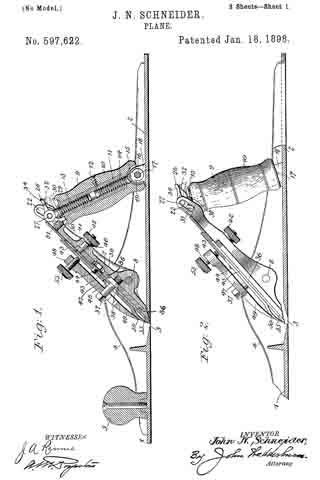
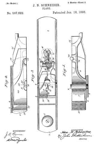
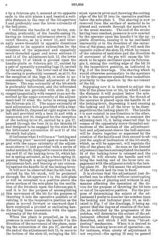
In the accompanying drawings, forming a part of this specification, Figure 1 is a central vertical section through my device, showing the bit in an operative position. Fig. 2 is a side elevation, partly in section, of a portion of a plane, showing the bit retired or in inoperative position. Fig. 3 is a top plan view with certain of the parts broken away. Fig.
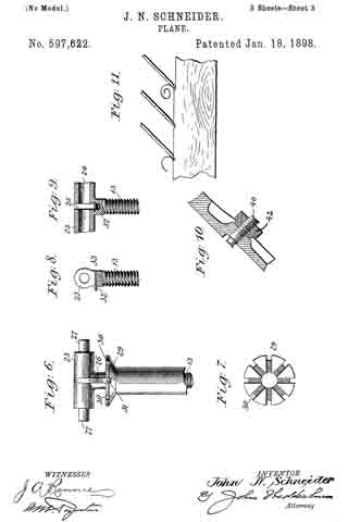
4 is a top plan view of a portion of the bit-stock and the mechanism supported thereby. Fig. 5 is a bottom plan view of the subject matter of Fig. 4, showing the lateral adjustment of the bit in dotted lines and illustrating a modified form of the fulcrum-pin. Fig. 6 is a detail view of a portion of the adjustment-sleeve index and locking-plate and the upper section of a bit-stock-adjusting bolt. Fig. 7 is a plan view of my indicator and locking-plate. Figs. 8 and 9 are detail views of the upper extremity of the bit-adjusting bolt. Fig. 10 is a view of a modified form of the mechanism comprehended by the parts 40 and 42. Fig. 11 is a diagrammatic view illustrative of the edect of the ordinary manipulation of the plane upon the cutting edge of its bit.
Referring to the numerals on the drawings, 1 indicates a plane-stock consisting, as usual, of a sole-plate 2, provided with a transverse bit-aperture 3 and with frame or side pieces 4, preferably of the configuration illustrated.
5 indicates the front guiding knob or handle, secured upon the sole-plate in the usual manner, and 6 indicates a bit-stock consisting of a bed-plate 7, provided with a bit-iron and its retaining and lateral adjusting mechanism and fulcrumed between the side pieces 4 by a fulcrum-pin 3, secured at its opposite ends to the side pieces 4 and located a suitable distance to the rear of the bit-aperture 3 and preferably near the lower extremity of the bed-plate.
9 indicates the handle of my device, consisting, preferably, of the handle-casing 10, having an internal adjustment-sleeve 11. secured thereto, as by a screw 12, and internally screw-threaded in opposite directions adjacent to its opposite extremities for the reception of the separated and oppositely screw-threaded upper and lower sections 13 and 14; of the adjustment-bolt 15, the lower extremity 16 of which is pivoted upon the handle-pintle or fulcrum-pin 17, carried by a pair of upwardly-extending lugs 13, carried by the sole-plate. The lower end of the handle-casing is preferably recessed, as at 19, for the reception of the lugs 13, in order to accommodate longitudinal adjustment of the former. The rear extremity of the bit-stock is preferably bifurcated, and the bifurcated extremities are provided with slots 22, arranged tangentially with respect to an are described by the upper extremity of the adjustment-bolt 15 when the latter is swung upon the fulcrum-pin 17. The upper extremity of said adjustment-bolt is provided with a bearing-thimble 23, disposed at right angles to the bolt and provided with a bore 24: and with a transverse slot 25, designed for the reception of the locking-lever 26, carried by a pin 27, passed through the bore 24 in the thimble 23 and designed to be engaged by the slots 22 in the bifurcated extremities 20 and 21 of the bit-stock bed-plate.
29 indicates what I will term a “locking and indicating plate” secured upon or made integral with the upper extremity of the adjustment-sleeve 11 and provided with a series of radial notches 30, designed to receive the locking end 31 of the locking-lever 26, which latter is spring-actuated, as by a bent spring 32, passing through a spring-aperture 33 in the adjustment-bolt, and bearing at one extremity against the handle 34 of the locking-lever.
It will now be observed that the bit-iron 35, carried by the bit-stock, will be projected through the bit-aperture 3 in the sole-plate or will be retracted to a position above the lower surface of the sole-plate by the oscillation of the bit-stock upon the fulcrum-pin 3, and it is for the purpose of accomplishing this movement of the bit for the purpose of throwing it into the operative position or of retiring it to the inoperative position as the plane is moved forward or rearward that I have employed a pivoted or oscillating handle having loose connection with the upper extremity of the bit-stock.
When the plane is propelled, as in use, pressure is exerted upon the handle 9 in the direction of the movement of the plane, causing the extremities of the pin 27, carried at the end of the adjustment-bolt 15, to move to the bottom of the slots 22, swinging the bit-stock upon its pivot and throwing the cutting edge of the bit 35 into its operative position below the sole-plate 2. The shaving is now removed from the surface of material to be planed and extends through the aperture 3 in the usual manner. The end of the stroke having been reached, pressure is now exerted by the operator upon the handle 9 in the opposite direction, causing it to be oscillated rearwardly or in the direction of the retraction of the plane, and the pin 27 will seek the opposite ends of the slots 22, which by reason of the relation of said slots and the direction of movement of the pin will cause the bit-stock to be again oscillated upon its fulcrum-pin 8, raising the cutting edge of the bit 35 to the inoperative position, as indicated in Fig. 2 of the drawings. The shaving which would otherwise accumulate in the aperture 3 is by this operation ejected from immediate proximity to the aperture by the movement of the bit.
Supposing now it is desired to adjust the bite of the plane iron or bit, by which I mean the distance it will project below the sole-plate in the operative position, the thumb of the operator is placed upon the handle 34: of the locking-lever, depressing it and causing the locking end 31 of the lever to be disengaged from the locking-plate 29. The handle 9 is now rotated in one direction or the other, as it is desired, to lengthen or contract the adjusting-bolt 15, it being observed that by reason of the oppositely screw-threaded connections of the sections of the adjustment-bolt and adjustment-sleeve the bolt-sections will be drawn together or separated by the rotation of the handle and thus caused to adjust the angle of inclination of the bit-stock, which, as will be apparent, will regulate the bite of the plane-bit. As soon as the desired adjustment has been accomplished the handle 34 of the locking-lever is released and the spring 32 will elevate the handle and will bring the locking end of the lever into engagement with the adjacent notch in the locking-plate 29. By this means the adjustment of the bit-stock and its iron is fixed.
It is obvious that the adjustment just described can be effected without interrupting the operation of planing and without in any manner affecting the operation of the device for the purpose of throwing the bit into or out of its operative position. For the purpose of determining the extent of the adjustment I prefer to number the notches upon the looking and indicator plate 29, as indicated in Fig. 7 of the drawings, it being apparent that the degree of rotation of the handle, as indicated by the progression of the notches, will determine the extent of the adjustment effected through the mechanism described, and which I will term “bit-adjusting” mechanism. When it is desired to throw the locking-lever out of operation — as, for instance, when nicety of adjustment is not required — the spring 32 may be passed through the aperture 33 to the position indicated in dotted lines of Fig. 1 of the drawings, in which position it will hold the locking end of the locking-lever out of operation, and the handle may then be turned in either direction at will.
Having now described the bit-actuating mechanism and the bit-adjusting mechanism, I shall now proceed to a description of the novel mechanism by means of which the bit or iron is adjustably secured upon the bed-plate of the bit-stock.
36 indicates a bit-supporting plate pivotally secured to the face of a depressed portion of the bit-stock by means of a bit fulcrum-bolt 37, screwed into the bed-plate 7 at a point adjacent to the fulcrum-pin 8 and provided with a conoidal portion 38, designed to be received by a correlatively-shaped aperture 39 in a bit-supporting plate 36.
40 indicates the bit-adjustment bolt, secured at one extremity to the plate 36 near its end and projecting through a curved aperture 41, designed to accommodate its movement in the bed-plate 7, incurred in a degree corresponding to the arc of movement of the adjustment-bolt.
42 indicates a thumb-nut screwed upon the extremity of the bolt 40 and designed by its abutment against the lower surface of the bed-plate to secure the bolt in its adjusted positions in the manner hereinafter made apparent. The iron or bit 35 is now placed upon the surface of the stock and the plate 36 and is secured to the superimposed cap-iron 43 by the screw-bolt 44, the head of which its closely within an aperture in the plate 36 to prevent lateral movement of the bit and cap iron upon said plate, an elongated recess being provided in the surface of the stock to permit the movement of the head ot the bolt 44, when the plate 36 is swung upon the pivot for the purpose of alining the cutting edge of the bit with the surface of the sole-plate 2. The bit-iron is provided with an elongated slot 45, designed to accommodate the bolt 37 when the bit is moved longitudinally, and the cap-iron 43 is provided with an aperture 46, through which said bolt is passed, as illustrated.
47 indicates a compression-lever provided with a pointed extremity 49, designed to bear against the spring end 50 of the cap-iron, which bears against the bit adjacent to its cutting edge. The compression-lever is preferably provided with an aperture 51, correlative in size and shape with the hexagonal head of the bolt 37 and designed to permit the same to be passed therethrough, and with a preferably small recess 52, extending from the aperture 51, into which recess the bolt proper is slipped, as indicated in Figs. 1 and 4 of the drawings.
53 indicates a compression-bolt screwed to the rear end of the compression-lever and designed to abut against the cap-iron. It will thus be seen that the bit is clamped firmly against a suitable bit-supporting plate 36 and may be swung upon the bolt 37, as indicated in dotted lines in Fig. 5, for the purpose of alining the cutting edge of the bit with the surface of the sole-plate 2.
Summarizing briefly, I have by the construction and arrangement described and illustrated produced a plane provided with means for the lateral and longitudinal adjustment of the bit upon the bit-stock, mechanism for adjusting the bit-stock through the movement of the handle, and mechanism for actuating the bit-stock to throw the bit into or out of operative position automatically as the plane is propelled or retracted, as in use.
I do not desire to limit myself to the details of construction herein shown and described, but reserve to myself the right to change, modify, or vary such details within the scope of my invention.
Having thus described my invention, what I claim as new, and desire to secure by Letters Patent, is —
1. The combination with a plane-stock, bit and oscillatory bit-stock, of a rotary and oscillatory handle operatively connected with the bit-stock, means whereby its oscillation will actuate the bit-stock, and whereby its rotation will adjust its connection therewith, substantially as specified.
2. The combination with a plane-stock, bit and oscillatory bit-stock, of a rotatable plane-handle operatively connected with the bit-stock and means for causing its rotation to adjust its connection with said bit-stock, substantially as specified.
3. The combination with a plane-stock, bit and oscillatory bit-stock, of an oscillatory handle and a slot-and-pin connection between the upper extremity of the handle and bit-stock, substantially as specified.
4. The combination with a plane-stock, bit and oscillatory bit-stock, of an oscillatory handle, bit-adjusting mechanism actuated by the movement of the handle and means carried by the handle for locking said bit-adjusting mechanism, substantially as specified.
5. The combination with a plane, a bit and oscillatory bit-stock, of a rotary handle operatively connected with the bit-stock and designed by its rotation to adjust the same, of an index and locking plate operatively connected with the handle, and a locking-lever operatively connected with said plate, substantially as specified.
6. The combination with a plane-stock, of an oscillatory bit-stock, an oscillatory handle, bit-stock-adjusting mechanism intermediate the handle and bit-stock, a bit adjustable upon the bit-stock, and locking mechanism intermediate of the handle and bit-stock, substantially as specified.
7. The combination with a plane-stock, bit and oscillatory bit-stock, of an oscillatory handle and a sectional adjustment-bolt operatively connected with the handle and with the bit-stock, substantially as specified.
8. The combination with a plane-stock, bit and oscillatory bit-stock, of a sectional adjustment-bolt pivoted upon the plane-stock and operatively connected with the bit-stock, a handle operatively connected with the adjustment-bolt and cooperating locking mechanism carried by the bolt and handle, substantially as specified.
9. The combination with a plane-stock, bit and oscillatory bit-stock, of a sectional oscillatory adjustment-bolt connected with the bit-stock by a slot-and-pin connection, a handle operatively connected with a sectional adjustment-bolt, an indicator and locking-plate carried by the handle and a locking-lever carried by the bolt, substantially as specified.
10. The combination with a plane-stock, bit and oscillatory bit-stock, of a sectional adjustment-bolt operatively connected with the bit-stock, a handle operatively connected with the bolt, a notched indicator and locking-plate carried by the handle, a locking-lever carried by the bolt and a spring designed to be adjusted for the purpose of causing it to actuate the locking-lever or to prevent such actuation, substantially as specified.
In testimony whereof I have signed this specification in the presence of two subscribing witnesses.
JOHN N. SCHNEIDER.
Witnesses:
JOHN W. KNAUER,
EMIL J. HESS.