
| PLEASE NOTE: The images presented on this page are of low resolution and, as a result, will not print out very well. If you wish to have higher resolution files then you may purchase them for only $2.95 per patent by using the "Buy Now" button below. All purchases are via PayPal. These files have all been cleaned up and digitally enhanced and are therefore suitable for printing, publication or framing. Each zip package contains all the images below (some packages may contain more), and purchased files can be downloaded immediately. |
UNITED STATES PATENT OFFICE.
_________________
JOHN BRANDELL, OF WALPOLE, NEW HAMPSHIRE.
PLANE.
_________________
SPECIFICATION forming part of Letters Patent No. 600,767, dated March 15, 1898.
Application filed August 5, 1897. Serial No. 647,180. (No model.)
_________________
To all whom it may concern:
Be it known that I, JOHN BRANDELL, of Walpole, in the county of Cheshire and State of New Hampshire, have invented certain new and useful Improvements in Planes; and I do hereby declare the following to be a full, clear, and exact description of the invention, such as will enable others skilled in the art to which it appertains to make and use the same.
This invention is an improvement in planes, and relates more especially to rabbeting-planes, the object of the same being to provide one that can be readily adjusted to increase and diminish the width of the rabbet or groove, and includes a guide for determining the depth of said groove and also certain devices for adjusting the bits, all as will be hereinafter fully set forth, and specifically pointed out in the appended claims.
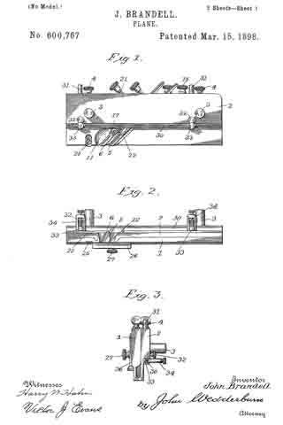
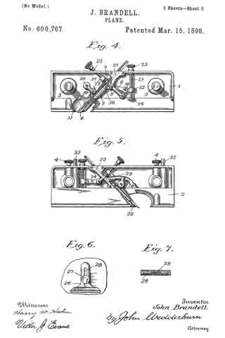
In the accompanying drawings, forming part of this specification, Figure 1 is a side elevation of a rabbeting-plane constructed in accordance with my invention. Fig. 2 is a view looking at the lower edge of the plane. Fig. 3 is an end elevation. Fig. 4 is a detail view of one of the sections of the plane removed, including the parts carried thereby. Fig. 5 is a similar view of the other section of the plane. Fig. 6 is a side elevation of part of section 1, showing the gage-plate. Fig. 7 is an end view of gage-plate.
Referring more particularly to the drawings, 1 and 2 designate the two sections of the plane which form the sides thereof and are connected by pins 3, which extend from one section through openings therefor in the other section, the parts being held adjustable with respect to each other by the set-screws 4, carried by the section 2 and engaging the pins which project from the section 1. The pins are each provided with a scale, for a purpose hereinafter set forth.
The inner sides of the sections 1 and 2 of the plane are hollowed out, the section 1 presenting an inclined rib 5, upon which bears a bit 6, having teeth 7, by which it is connected to an elbow-lever 8, pivoted upon a bearing-pin 9, supported at one end by a bracket 10, while its other end is let into the section. The lower or cutting edge of the bit is adapted to be projected below the rib 5, the section having a lateral projection 11, the surface of which is curved, as shown, to guide the shavings out of the plane. The elbow-lever, which is connected to the bit, as hereinbefore described, is operated by a block 12, mounted upon a screw 13, bearing at its lower end in a post 14 and extending through the upper part of the section 1, where it is provided with a knob or milled wheel 15. The connection between the sliding block and lever is by means of a projection 16 on the block engaging the bifurcated end of the lever. The block is prevented from turning upon the screw by bearing against the inner side of the section 1, and it will be observed that when the said screw is turned the bit will be raised or lowered to adjust the same.
The bit is securely clamped in position after being adjusted by means of a clamp consisting of the parts 17 and 18, one of which bears against the upper part of the bit, while the other bears against the lower part thereof, the said clamp being pivoted upon a bearing-screw 19, supported at one end by a bracket 20. The parts or members of the clamp are forced upon the bit by means of a screw 21 engaging a threaded aperture in the projecting end of one part and bearing upon the projecting end of the other part, serving to force the latter directly against the bit, while drawing up upon the other part of the clamp in forcing its opposite end against the bit. It will be understood, of course, that before adjusting the bit the clamp is released, and by the particular construction and arrangement described a minute adjustment can be secured, the upper part of the bit being of a width to fit within the opening thereof and properly dispose the cutting edge with respect to the edge of the plane.
The section 2 of the plane carries mechanism for adjusting the bit which is similar in construction to that hereinbefore described, with the exception that the bit 22 is given further bearing-surfaces to prevent lateral movement, and to this end acasting 23 is secured to the rib 24, forming one of the bearings for said bit, the casting having projecting members supporting the pivot-pins of the mechanism. The bit carried by this section is so located with respect to the bit of the other section as to be located behind the same when the two sections are placed together.
By providing the plane with two sections movable to and from each other and having each section carry a bit the width of a groove to be cut by the plane can be increased or diminished by moving said sections to and from each other, the adjustment being held by thumb-screws, which engage the connecting-pins. In connection with the two bits each section is provided on its outer side with a cutting-blade 25, adjustable by having a slot through which a retaining-screw passes.
Upon one side of the plane is mounted a gage-plate 26, adjustable with respect to the edge of the plane by means of a thumb-screw 27 passing through a slot 28 therein and engaging a threaded aperture in the plane, gage-marks being provided, as shown, to indicate the extent of the adjustment, while the straight-edge of the gage-plate is maintained parallel with the edge of the plane by forming a rib 29 upon the inner side of the plate, which slides within a recess therefor in the plane. This gage-plate is for the purpose of determining the depth of the rabbet or groove.
I also provide the plane with a longitudinal guide-strip 30, connected to stems or pins 31, which slide within openings therefor in the side of the plane, the said guide-strip being held by thumb-screws 32, which engage the stems. When the guide-strip is projected below the bottom of the plane and held by the thumb-screws referred to, said strip may be adjusted inwardly under the body of the stock by screws carried by the strip and engaging threaded apertures in heads 33, formed at the outer ends of the pins, the screws rotatably engaging the strip at their inner ends and bearing at their opposite or outer ends in brackets 34, extending from the strip, the screws being held against longitudinal movement with respect to the strip and its brackets. When the guide-strip is extended below the edge of the plane, it will assist in forming a rabbet by bearing against the edge of the lumber or work. In forming a groove the guide-strip is slipped up out of the way, lying snugly against the longitudinal shoulder formed by the enlarged upper portion of the section 1 of the plane.
From the foregoing description, in connection with the accompanying drawings, it will be apparent that I provide a plane which is susceptible of numerous adjustments to not only vary the width of a rabbet or groove, but also to determine its depth, besides presenting a guide-strip which will be serviceable in preventing the plane cutting in when forming a rabbet.
Having thus described the invention, what is claimed as new is —
1. A rabbeting-plane comprising two sections, means for adjusting said sections to and from each other, and bits carried by each section, the bit of one section overlapping and being located in the rear of the bit of the other section, substantially as shown and for the purpose set forth.
2. A plane comprising two sections, pins carried by one section and extending through openings therefor in the other section, screws for holding the adjustment of the movable section, and bits carried by each section, the bit in one section being located in the rear of and overlapping the bit in the other section, substantially as shown and described.
3. A plane for the purpose set forth, comprising two sections adjustable to and from each other, overlapping bits carried by the sections and located one in front of the other, a gage-plate adjustable vertically upon one section, and a guide-strip attached to the other section, substantially as shown and described.
4. A plane comprising two sections adjustable to and from each other, overlapping bits carried by the sections and located one in front of the other, a gage-plate vertically adjustable upon one of the sections, a guide-strip connected to the other section by pins, and set-screws engaging the pins, substantially as shown and described.
In testimony whereof I have signed this specification in the presence of two subscribing witnesses.
JOHN BRANDELL.
Witnesses:
FRED PRENTISS,
CHARLES SLADE.