| PLEASE NOTE: The images presented on this page are of low resolution and, as a result, will not print out very well. If you wish to have higher resolution files then you may purchase them for only $2.95 per patent by using the "Buy Now" button below. All purchases are via PayPal. These files have all been cleaned up and digitally enhanced and are therefore suitable for printing, publication or framing. Each zip package contains all the images below (some packages may contain more), and purchased files can be downloaded immediately. |
UNITED STATES PATENT OFFICE.
_________________
FRANCIS WITZMANN, OF NEW YORK, N. Y., ASSIGNOR OF ONE-HALF
TO ALEXANDER MONAGHAN, OF NEW ORLEANS, LOUISIANA.
HAND-PLANER.
_________________
SPECIFICATION forming part of Letters Patent No. 643,313, dated February 13, 1900.
Application filed March 25, 1899. Serial No. 710,475. (No model.)
_________________
To all whom it may concern:
Be it known that I, FRANCIS WITZMANN, a citizen of the United States, residing in New York city, borough of Manhattan, State of New York, have invented certain new and useful Improvements in Hand-Planers, of which the following is a specification.
The object of my invention is to provide a planer that shall be capable of planing the heads of barrels, kegs, tubs, and the like, while assuring that the hands of the operator need not come in contact with the chime, and which shall also be capable of planing other surfaces.
The invention consists in the novel details of improvement and the combinations of parts, that will be more fully hereinafter set forth and then pointed out in the claims.
Reference is to be had to the accompanying drawings, forming part hereof, wherein —
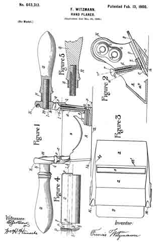
Figure 1 is a front view, partly in section, of a hand-planer embodying my invention. Fig. 2 is a vertical cross-section thereof. Fig. 3 is an inverted plan view of the planer. Fig. 4 is a detail and transverse sectional view of a clamp or wedge, and Fig. 5 is a detail sectional view of the handle.
In the accompanying drawings, in which similar letters of reference indicate corresponding parts in the several views, A indicates a frame of suitable construction, and which is shown provided with a bottom plate a, having a slot or opening a’, opposed side walls a2, and upwardly and outwardly inclined back wall J, upon which a blade B is adapted to rest so thatits lower cutting edge will project into or through the opening a’.
(See Fig. 2.)
C is a clamp or wedge that is adapted to bear upon the blade B to hold the latter in the operative position. Means are provided for retaining the clamp C in such position that its lower beveled edge will aline with and lie near the cutting edge of the blade B, and for this purpose I have shown the clamp C as provided with projections or tongues P, that are adapted to pass into grooves D in the walls a2, which grooves are shown parallel with the walls J and the blade B and above the latter, and the lower ends m, of these grooves form abutrnents, against which the ends l of projections or tongues P rest to regulate the distance that the clamp C can be pushed into the frame. The clamp is held in place so as to create a pressure upon the blade B by means of screws F, which mesh in threaded bores c in lugs d, cast on the inner faces of walls a2 and extending upwardly above the clamp C, the lower ends of these bores c opening above said clamp to enable the ends of the screws F to bear upon the clamp. (See Fig. 2.) The lower parts of lugs d are shown reduced to allow greater freedom for the passage of chips. In line with the bores c the clamp C is provided on its upper surface with countersunk recesses k, into which the tapered ends of the screws F fit.
From the foregoing it will be understood that the clamp C is retained in the lower working position by the projections or tongues P, engaging the abutments m, and that the screws F by entering the recesses k keep the clamp from slipping out of place. By forcing the screws F upon the clamp the latter will hold the blade B rigidly in the cutting position, and by slacking back the screws the pressure of the clamp upon the blade will be reduced and the blade can be readily adjusted more or less into the cutting position to make the desired depth of cut. It will also be seen that when the blade is withdrawn from the frame the clamp will still remain in the working position. As shown, the winged ends of screws F project above the upper edges of the sides a2 of the frame A in position to be readily operated, and the lower edge of the clamp can be seen through the top opening of the frame, whereby as the clamp remains in position it acts as a sight-guide in adjusting the cutting edge of the blade B to a true position transversely of the frame.
The side walls a2 of the frame A are carried high up from the lower wall a, and there is an open space between said walls, as shown in Fig. 1, and to these walls handles G are attached, which extend outwardly in opposite directions. The handles G are thus elevated sufliciently high so that the hands of the operator will not come in contact with the chime of a barrel, keg, or tub when the head of the same is being planed, and by this means practically the entire surface of the barrel-head (except for a slight distance inwardly from the chime) can be planed uniformly and smoothly or a brand or label readily planed or scraped from the same and a perfect command of the tool is afforded. Any suitable means may be provided for attaching the handles to the frame. I have shown a screw or threaded rod H, which meshes in threaded apertures I in the upper portion of the side walls of the frame, and the handles G have threaded apertures that mesh with the screws H, and by preference ferrules N surround the inner ends of the handles and abut, respectively, against shoulders on the handles and against the outer surface of the side walls a2.
The lower edges of the outer sides of the frame A are shown curved, so as to conform somewhat to the curve of the chime or flange of the barrel, keg, or the like whose head or cover is to be planed. (See Fig. 3.)
I do not limit my invention to the details of construction shown and described, as they may be varied without departing from the spirit thereof.
Having now described my invention, what I claim is —
1. In a hand-planer, a frame having an opening in its lower face for a blade and grooves in its side walls parallel to the plane of the blade-seat, combined with a clamp having projecting portions to engage said grooves, the ends of the grooves forming abutments to limit the downward movement of the clamp-plate, and screws carried in threaded apertures in the frame adapted to bear upon said clamp to press the same upon the blade, substantially as described.
2. In a hand-planer, a frame having an opening in its lower face for a blade and grooves in its side walls parallel to the plane of the blade-seat, combined with a clamp having projecting portions to engage said grooves, and provided with recesses on its upper face, the ends of the grooves forming abutments to limit the downward movement of the clamp-plate, and screws carried in threaded apertures in the frame adapted to enter the recesses in the clamp to retain the same in position in the frame and to press the clamp upon a blade, substantially as described.
3. In a hand-planer, a frame having a bottom wall and opposed side walls rising from the same, and means for retaining a blade in said frame, combined with a pair of handles each attached to and projecting laterally from the outer surface of one of said side walls at the top portion of said walls, substantially as described.
In testimony that I claim the foregoing as my own I have hereto affixed my signature in the presence of two witnesses.
FRANCIS WITZMANN.
Witnesses:
GEORGE HILL,
WM. H. HEINECKE.


