| PLEASE NOTE: The images presented on this page are of low resolution and, as a result, will not print out very well. If you wish to have higher resolution files then you may purchase them for only $2.95 per patent by using the "Buy Now" button below. All purchases are via PayPal. These files have all been cleaned up and digitally enhanced and are therefore suitable for printing, publication or framing. Each zip package contains all the images below (some packages may contain more), and purchased files can be downloaded immediately. |
United States Patent Office.
S. MARKEE, OF AUBURN, NEW YORK, ASSIGNOR TO HIMSELF AND JOHN M. EASTERLEY, OF SAME PLACE.
Letters Patent No. 64,341, dated April 30, 1867.
_________________
IMPROVEMENT IN PLANE-IRONS.
_________________
The Schedule referred to in these Letters Patent and making part of the same.
_________________
TO ALL WHOM IT MAY CONCERN:
Be it known that I, S. MARKEE, of Auburn, in the county of Cayuga, and State of New York, have invented a new and useful Improvement in Plane-Irons; and I do hereby declare that the following is a full, clear, and exact description thereof, which will enable others skilled in the art to make and use the same, reference being had to the accompanying drawings, forming a part of this specification, in which —
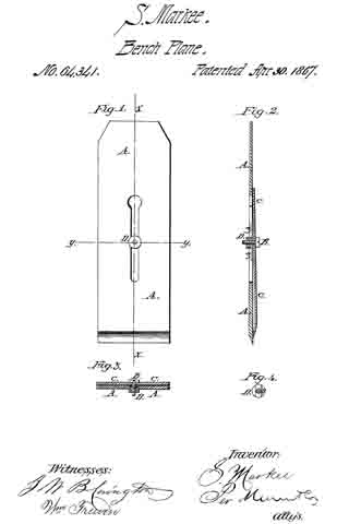
Figure 1 is an under side view of the plane-iron, showing the sliding-nut.
Figure 2 is a longitudinal section of the same, taken through the line x x, fig. 1.
Figure 3 is a cross-section of the same, taken through the line y y, fig. 1.
Figure 4 is a detail sectional view, taken through the line z z, fig. 2, showing the under side of the sliding-nut.
Similar letters of reference indicate like parts.
My invention has for its object to furnish an inaproved double plane-iron, simple and cheap in construction, and convenient in operation; and it consists, first, in attaching the cap to the plane-iron by a screw and sliding-nut; and, second, in the sliding-nut in combination with the plane-iron cap and screw, as hereinafter more fully described.
A is the plane-iron, which has a longitudinal slot, as shown, for the passage of the screw B, which secures the cap C to the plane-iron. The upper end of this slot is enlarged so that the nut D can he passed through it.
The cap C is made of sheet steel, slightly curved in its lower part, as shown in fig. 2. Through this cap is made a hole for the passage of the screw B. The screw B passes through the cap C and through the slot in the plane-iron A, and screws into the sliding-nut D, as shown in fig. 2. This nut is made with a projecting part or flange, as shown in figs. 2, 3, and 4, which its into the slot formed in the plane-iron A, and slides along said slot in adjusting the cap C upon the plane-iron A. By this construction it is not necessary to make the cap C as heavy as it was formerly made, when it had to be made thick enough to receive and hold the screw that held the cap and plane-iron together. This construction enables me to place the head of the screw on the upper side of the plane-irons, making it much more convenient to adjust the cap in proper position with reference to the cutting edge of the plane-iron than when the head of the connecting-screw was on the under side of the plane-iron, as was the case when the cap and plane-iron were connected together in the ordinary manner.
What I claim as new, and desire to secure hy Letters Patent, is —
The plane-iron, consisting of the slotted iron A, curved cap C, flanged sliding-nut D, and screw B, arranged and operating substantially as described for the purpose specified.
The above specification of my invention signed by me this 7th day of March, 1866.
S. MARKEE.
Witnesses:
B. J. IVES,
R. P. STOW.


