
| PLEASE NOTE: The images presented on this page are of low resolution and, as a result, will not print out very well. If you wish to have higher resolution files then you may purchase them for only $2.95 per patent by using the "Buy Now" button below. All purchases are via PayPal. These files have all been cleaned up and digitally enhanced and are therefore suitable for printing, publication or framing. Each zip package contains all the images below (some packages may contain more), and purchased files can be downloaded immediately. |


UNITED STATES PATENT OFFICE.
_________________
JUSTUS A. TRAUT, OF NEW BRITAIN , CONNECTICUT.
BENCH-PLANE.
_________________
SPECIFICATION forming part of Letters Patent No. 645,220, dated March 13, 1900.
Application filed December 10, 1897. Serial No. 661,391. (No model.)
_________________
To all whom it may concern:
Be it known that I, JUSTUS A. TRAUT, a citizen of the United States, residing in New Britain, in the county of Hartford and State of Connecticut, have invented certain new and useful Improvements in Planes, of which the following is a specification.
This invention relates to planes, and especially to knife-adjusting means therefor; and it has for its main object the provision of an improved tool of this type in which the knife can be set quickly in an adjusted position and held firmly in place without the use of adjusting-levers, the construction being such that all of the parts can be separated and assembled with great rapidity and precision.
My present improvements are designed more particularly for use in connection with planes of that type in which the knife or plane-bit is disposed at a comparatively-small angle with respect to the sole of the plane, thereby leaving but a small space at the rear end or heel of the plane for the knife adjusting and holding devices, and it is of the utmost importance in tools of this kind to provide holding and adjusting means which may be assembled and disassembled readily and operated a minimum distance for the purpose of effecting the proper adjustment of the plane-knife. It is essential, of course, that all of these parts should be so organized that the knife will be held firmly in place when set in any adjusted position, or else the adjustment of the bit might be changed and the proper operation of the tool prevented.
In the plane illustrated in the drawings of this application I have illustrated devices for obtaining two different adjustments of the plane knife or bit — one a rough adjustment, by means of which the knife may be brought quickly approximately to its proper position, and a fine adjustment, which will be effected, preferably, by means of a suitable adjusting-screw.
The device which I employ for obtaining the fine adjustment of the plane-bit constitutes one of the main features of this invention, and I may employ for this purpose an adjusting-screw having two diderent threads thereon, one of which coacts with a suitable member of the plane-bit and the other with the knife or its carrier. In this instance the knife is supported on a slide which will have a supporting-face oblique to the sole of the plane and will be shifted toward and from such sole by means of an adjusting-screw of the kind just described. Preferably the adjusting-screw will have two similar threads of different pitch, one of which will engage a fixed member of the body of the plane and the other of which will engage the slide, the parts being so organized that when the screw is turned it will move in the same direction through both the slide and the supporting member of the plane-bit and will at the same time cause the slide to be shifted toward and from such supporting member in accordance with the direction of movement of the screw.
The screw which I employ will be of two diameters in order that the smaller diameter thereof, which is at the point, may admit of the insertion of the reduced part through a proper threaded opening or fixed nut in the plane-bit; but the threads of the portion of the screw which is of larger diameter engage the corresponding internal threads of the member or fixed nut on the body of the plane. Hence it will be evident that in assembling the parts the reduced end of the screw may be passed through the threaded member of the plane-body and the point of the screw then inserted in the proper threaded opening or fixed nut of the slide, whereupon the screw may be turned into the two parts simultaneously by the turning of two similar threads of different pitch in the same direction, and thus draw the slide toward the supporting member of the plane-body while the screw is advancing through the threaded member or fixed nut of the latter. It will be noticed that this movement of the slide toward the fixed member on the body is due to the fact that the thread at the forward end of the screw is of quicker pitch than that near the head of the screw.
For the purpose of effecting the coarse adjustment of the plane-knife said knife and its support will have coacting holding members, one of the parts having a single holding member and the other a series, although each of the members of said series is adapted to engage said single holding member, so as to lock the plane-knife roughly in any desired position with respect to the throat of the plane. Usually the knife-support, which in this case will be the slide, will have a stop or rib projecting therefrom and adapted to enter any one of a longitudinal series of recesses in the plane-bit, these recesses being preferably in the form of parallel transverse grooves in the under side of the knife. It will be clear that these coacting holding means will permit a rough adjustment of the knife approximately in the desired position and that the fine adjustment may be effected afterward by means of the screw. Moreover, when the knife has such a row of recesses or grooves therein as that just described it will be apparent that the knife may be used in connection with planes of several different sizes, which is a matter of considerable importance.
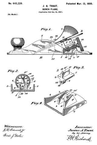
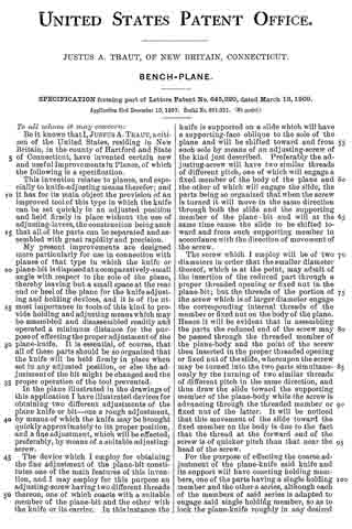
In the drawings accompanying and forming part of this specification, Figure 1 is a sectional side elevation of a plane constructed in accordance with my present improvements. Fig. 2 is a transverse section of the plane-body and the slide, the section being taken in the line 2 2, Fig. 1, looking toward the heel of the plane. Fig. 3 is a perspective view of the knife supporting and adjusting slide, and Fig. 4 is a perspective view of the rear end or heel of the plane-body and illustrates the supporting member or guide on which the knife-adjusting slide is mounted.
Similar characters designate like parts in all the figures of the drawings.
As to many of the features thereof the body of the plane illustrated herein is similar to plane-bodies as ordinarily constructed. In this case the plane-body (designated in a general way by B) embodies as its essential features a flat base or sole s, side walls 2 2, and a support or guide, such as g, on which the slide will be carried. This guide may be of any suitable construction and is substantially U-shaped in this case in horizontal section and has a pair of oblique supporting-faces 3 3, on which the slide may move. At the inner side of the two side walls 4 4 of the guide I have illustrated a pair of channels or grooves 5 5, forming, with the oblique faces 3 3,ways for locating and guiding the slide.
As before stated, the knife or plane bit is intended to be supported on a slide shiftable by means of a feed-screw in order to obtain the fine adjustment of the knife, and this slide is indicated by S. It may be of any suitable construction, but in this case will have a pair of channels or grooves 6 6 in the under side of the main or fiat portion 7 thereof, these grooves being parallel to each other and so disposed as to cooperate with the guide-faces 3 3 and the grooves 5 5, as will be evident by referring to Fig. 2. It will be clear that this slide moves on the ways of the guide g toward and from the sole of the plane in a path oblique to such sole, this method of mounting the slide being well understood.
For the purpose of shifting the slide in the manner described I have illustrated at f 2 feed-screw of the type which has been hereinbefore referred to, the body portion of this screw being of two diameters and one portion having right-hand threads of one pitch and the other having corresponding threads of a different pitch. In this case it will be clear that the threads 10 are of a relatively-slow pitch, while the threads 12 are of somewhat-quicker pitch, and hence will be capable of shifting the slide with which they codperate so as to move said slide toward and from the back wall 13 of the guide g, in which back wall the feed-screw is mounted so as to lie obliquely to the sole s. The wall 13 of the guide is bored and screw-threaded to correspond with the threads 10 and form a fixed nut, in which the larger portion of the screw may work, while the slide S will have in this case a fixed nut in the form of a depending lug 14, internally screw-threaded to cooperate with the threads 12 of the point of the screw f. When the parts are properly fitted, the slide S may be shifted longitudinally of the slide-supporting faces of the guide, but will be held down and will be prevented from rising by reason of its connection with the screw f, which is braced firmly, and will be supported by the guide in such a manner that it will have no movement except in the direction of its length.
In assembling the parts the feed-screw, which will usually have a milled head, such as 15, of relatively-large diameter for the purpose of turning the screw freely, will be inserted through the opening 13′ until the threads 10 come into engagement with the threads of such opening, and the point of the screw will then be inserted into the opening 14′ in the fixed nut of the slide from the rear side thereof when the slide is in its extreme forward position on the ways of the guide. When the screw is turned to the right, the threads 10 will turn forward and the feed-screw will gradually pass through the opening 13’ toward the throat of the plane, and at the same time the threads 12 will turn forward in the fixed lug 14 of the slide and by reason of their quicker pitch will cause the slide to shift toward the wall 13. It will be seen that by employing a feed-screw of this type the assembling of the slide, the feed-screw, and the plane-body will be effected with a minimum movement of the slide on the guide g, since the screw advances into both of the fixed nuts in the same direction and does not, as is the case with a right and left hand screw, have to be inserted into one side of one nut and into the other side of the other nut. Hence the slide can be put in place approximately in its proper position, and its screw then turned into both of the fixed nuts a relatively-slight distance to position properly the knife to be supported and adjusted by the slide. This form of feed-screw and cooperating fixed nuts and the manner of assembling the parts described are of distinct utility, especially in those planes of the type illustrated herein having their knives set at a very slight angle to the sole, leaving but a small amount of available space between the rear end of the knife and the heel of the plane. By employing the devices shown herein this space is utilized to the best advantage, and all of the parts are of ample size and strength to operate properly and hold the bit firmly.
The plane knife or bit is indicated by k and may be of any suitably type. This knife and the slide S are intended to have coacting holding members, such as those hereinbefore described, for effecting the coarse adjustment of the bit. The holding member of the slide is indicated at 16 and is in the form of a stop or rib rising from a central wall or larger rib 17 of the slide S, the face 17′ of this wall or rib constituting the supporting-face on which the upper or rear end of the knife is carried. The other holding members, which cooperate with the stop or rib 16, are carried by the knife k and in the construction shown are in the form of a series of recesses or parallel transverse grooves 18 in the under side of said knife, these grooves forming between them transverse stops or ribs substantially similar to the ribs 16, the groove 18 being just large enough to receive the rib 16 and leave no extra space.
It will be clear that after the slide and its feed-screw are in place on the plane-body a rough adjustment of the knife may be obtained by simply placing the proper groove 18 over the stop 16 and placing the knife down upon the supporting-face 17′ of the guide. After this coarse adjustment is obtained the knife should of course be clamped firmly to the slide S, after which the adjusting-screw f may be turned to effect the fine adjustment of the knife.
Any suitable clamping means may be employed for holding the knife in place. That shown herein is indicated in a general way only and will preferably be of the type fully shown and described in Letters Patent No. 591,663, dated October 12, 1897. This main clamping device is in the form of a cam-lever (indicated by 20) carried by a knife clamp or plate c of ordinary construction, this latter being mounted at its forward end on a fixed part, such as 22, of the plane-body by means of a screw-and-slot connection, such as 23, of the usual type. This screw 23 serves to prevent sidewise movement of the forward end of the knife, while the cam-lever by raising the rear end of the knife-clamp c wedges the rear end of the clamp and the knife together and also forces the forward end of the clamp against the knife near the throat of the plane to hold the parts firmly in place.
After the rough adjustment of the bit has been obtained and the latter has been clamped in place by the means just described the screw f will be turned to obtain the iine adjustment of the knife, and it will be noticed that during this last-mentioned adjustment the part which operates directly to effect such adjustment of the bit is not only movable, but supports the knife directly and guides it, thus rendering unnecessary the employment of other or separate means for such purpose.
Having described my invention, I claim —
1. In a plane, the combination, with a plane-body comprising a sole and a pair of side walls, said sole having rigid with the inner face thereof a U -shaped slide-supporting guide the side walls of which extend in parallelism with the body side walls and have their upper edges inclined and recessed to form ways, and connected at their outer ends by an end wall having an internally-threaded opening; a slide mounted on said guide and recessed at its edges to cooperate with said ways, and provided at its under side with an internally-threaded depending lug working intermediate said side walls and on its upper side with a longitudinally-extending centrally-located rib having a transversely-extending rib or projection; a knife adapted to be clamped on said rib and provided with a plurality of transversely-extending recesses for the reception of said transverse rib to locate the knife in position; an adjusting-screw of different diameters working in said guide and slide and having two sets of similar threads of different pitch; and means for clamping the knife in position on said slide.
2. In a plane, the combination, with a plane-body comprising a sole and a pair of side walls, said sole having rigid with the inner face thereof a slide-supporting guide the side walls of which extend in parallelism with the body side walls and have their upper edges inclined, and which walls support at their outer ends a member having an internally-threaded opening; a slide mounted on said guide and provided at its under side with an internally-threaded depending lug working intermediate said side walls and on its upper side with a longitudinally-extending centrally-located rib; a knife adapted to be clamped on said rib, said knife and rib having, one a projection, and the other recesses cooperating with said projection to locate said knife in position; an adjusting-screw of different diameters working in said guide and slide and having two sets of similar threads of diderent pitch; and means for clamping the knife in position on said slide.
JUSTUS A. TRAUT.
Witnesses:
H. S. WALTER,
W. J. WORAM.