
| PLEASE NOTE: The images presented on this page are of low resolution and, as a result, will not print out very well. If you wish to have higher resolution files then you may purchase them for only $2.95 per patent by using the "Buy Now" button below. All purchases are via PayPal. These files have all been cleaned up and digitally enhanced and are therefore suitable for printing, publication or framing. Each zip package contains all the images below (some packages may contain more), and purchased files can be downloaded immediately. |

UNITED STATES PATENT OFFICE.
_________________
HERBERT M. COE, OF PHOENIX, ARIZONA TERRITORY.
WOOD-PLANE.
_________________
SPECIFICATION forming part of Letters Patent No. 646,262, dated March 27, 1900.
Application filed May 2, 1899. Serial No. 715,322. (No model.)
_________________
To all whom it may concern:
Be it known that I, HERBERT M. COE, of Phoenix, in the county of Maricopa and Territory of Arizona, have invented a new and Improved Wood-Plane, of which the following is a full, clear, and exact description.
This invention relates to improvements in planes or spoke-shaves adapted for planing or shaving around circular bodies; and the object is to provide a tool of this character of simple yet strong construction that may be quickly adjusted to operate on flat surfaces or on curved surfaces of any radius.
I will describe a wood-plane embodying my invention and then point out the novel features in the appended claim.
Reference is to be had to the accompanying drawings, forming a part of this specification, in which similar characters of reference indicate corresponding parts in all the figures.
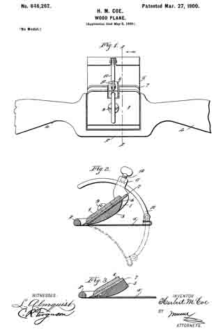
Figure 1 is a top plan view of a wood-plane embodying my invention. Fig. 2 is a section on the line 2 2 of Fig. 1, and Fig. 3 is a similar section of a slightly-modified construction.
Referring to the drawings, 1 designates a frame of suitable material — such, for instance, as metal — the side portions of which are curved upward and rearward, and at the front these side portions are connected by a cross-bar 2, and inward of the cross-bar is a cross-block 3. The space between the block 3 and the inner edge or side of the cross-bar 2 forms the throat of the tool. The frame is provided with oppositely-extended handles 4, so that the tool may be used as a spoke-shave. Extended rearward from and underneath the block 3 is a bed-plate 5, which bed-plate extends entirely across the frame or that portion of the frame occupied by the block 3, and it is made of spring material. In Fig. 2 I have shown it secured to the tool by having a portion 6 extended between the upper surface of the block 3 and the cutting-bit 7, which is held in place by the usual plate 8 and screw 9. In Fig. 3, however, I have shown the plate 5 as having its forward edge riveted to the forward end of the block 3.
Pivotally connected to the rear edge of the base-plate 5 is a curved arm 10, which passes through an opening in a lug 11 on the frame 1 and having a clamping-screw 12. In operation the tool may be employed for operating upon flat surfaces, and in such case the bed-plate will be arranged as indicated in full lines in Fig. 2. When it is to be used upon cylindrical or similar curved surfaces, the bed-plate 5 may be deflected to any desired degree to conform it to the shape or size of the article operated upon by moving the arm 10 through the lug 11 and clamping it by the screw 12.
While I have indicated in dotted lines in Fig. 2 a position for the plate 5 when the tool is to be used upon the exterior of a cylindrical body, it is obvious that the plate may be deflected in the opposite direction, so that the tool may be used on the inner side of a cylinder or the like.
Having thus fully described my invention, I claim as new and desire to secure by Letters Patent —
A wood-plane, comprising a frame, a cross-block in said frame upon which the plane-bit is designed to be secured, a flexible bed-plate extended rearward from said cross-block and having at its front end a portion extended upward between the block and bit and secured between the same, a curved arm having pivotal connection with the rear end of the plate, a perforated lug on the frame through which said arm may move, and a clamping-screw in the lug, substantially as specified.
HERBERT M. COE.
Witnesses:
J. C. DAVIS,
C. H. DAVIS.